Table of Contents
Advertisement
Installation & Operating Manual
Vision
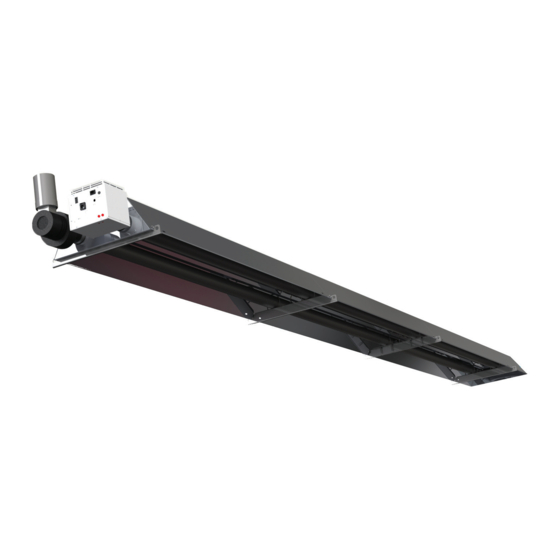
VS Radiant
Radiant Tube Heater (Propane)
Warnings
Nortek Global HVAC equipment must be installed and
maintained in accordance with the requirements of the
Codes of Practice or rules in force.
All external wiring must comply with the codes of
practice or rules in force in the country of installation.
Improper installation, adjustment, alteration, service or
maintenance can cause property damage, injury or death.
Read instructions before installing or servicing this
equipment. For use with all Vision VS models with
Generation code BB & BC. Gas-fired appliances are not
designed for use in hazardous atmospheres containing
flammable vapours or combustible dust, containing
chlorinated or halogenated hydrocarbons, or in
applications with airborne silicone substances.
Manual Part No.
Reznor® is a registered trademark of Nortek Global HVAC, LLC.
D301178 Issue A
ErP Lot 21
Seasonal Efficiency &
NOx compliant
Advertisement
Table of Contents

Related Manuals for Reznor VSUTE series


Summary of Contents for Reznor VSUTE series
- Page 1 ErP Lot 21 Manual Part No. D301178 Issue A Seasonal Efficiency & NOx compliant Reznor® is a registered trademark of Nortek Global HVAC, LLC.
- Page 2 IMPORTANT NOTICE TO INSTALLERS Installers should satisfy themselves that Do not use this appliance if any part has responsible for their safety. Children should the fuel pipework installation is carried out been immersed in water. Immediately call be supervised to ensure that they do not in accordance with all current legislation, a qualified service technician to inspect the play with the appliance.
-
Page 3: Table Of Contents
CONTENTS PAGE Installation requirements Commissioning 1.1 Health and Safety 3.1 Tools Required. 1.2 Model Definitions 3.2 Balance the Herringbone System 1.3 General requirements 3.3 Balancing a DLE System 1.4 Delivery and Pre-Installation checks. 3.4 Gas valve adjustment 1.5 Heater Suspension 3.5 Commissioning chart for VS series unitary heaters 1.6 Wall/Angle Mounting Servicing instructions... -
Page 4: Installation Requirements
Welcome Welcome to the new range of high efficiency When assembling, installing, commission- PLEASE READ: Vision radiant tube heaters. Local regula- ing and servicing is undertaken on radiant tions may vary in the country of use and it tube heaters specified in these instruc- Read this document prior to installation to is the installers responsibility to ensure that tions, due care and attention is required to... -
Page 5: Model Definitions
1.2 Model Definitions Any unauthorised modifications to the • The position of the heater relative to appliance, or departure from the manu- service and maintenance requirements WARNING • VSUTE = Vision U Tube heater with facturers guidance on the intended use, painted induced burner, aluminised steel or, installation contrary to the manufac- The heater must not be installed within... - Page 6 Linear Chain U Tube U Tube Chain length Linear length Linear Chain length Heater Size Required angle Eye bolt position 1 Chain length Eye bolt position 10 Eye bolt position 1 Chain length Eye bolt position 6 Eye bolt position 8 15 - 25 45°...
-
Page 9: Herringbone Systems (Uhe & Lhe)
1.7 Herringbone systems (UHE & LHE) The manifold system should be arranged to to take place and prevent stress and strain cap should be sealed with silicon jointing fall slightly in the direction of the vacuum on the system. compound and pop riveted in position. fan. - Page 10 Where a conventional flue is to be installed, the manufacturer can supply an aluminium transformation piece to which a 150mm (6ins) diameter flue must be attached. The length of flue which may be connected to the fan outlet must be adequately supported from the building structure.
- Page 11 Flexible connection Flue to atmosphere Return bend Reflector System damper assembly End caps Turbulator Burner control assembly Vacuum Fan Suspension brackets Secondary condensate drain is recommend Centre bracket Exhaust manifold Damper assembly Condensate drain Heater tail pipe branch Damper assembly End caps Turbulator Suspension...
-
Page 12: Clearance To Combustibles
1.8 Clearance to Combustibles A/A1 The minimum clearances to combustible materials are given in the tables below. CAUTION These minimum distances must be adhered to at all times The stated clearance to combustibles represents a surface temperature of 50°C WARNING above room temperature. -
Page 13: Gas Connection And Supply Details
1.9 Gas Connection and Supply Details connection must not be used. The complete It is also important to ensure that expansion Before installation, check that the local installation must be tested for soundness is taken up in the body of the flexible hose, distribution conditions, nature of gas as described in the country of installation. -
Page 14: Electrical Connection
Figure 12. Figure 13. The methods shown in the above figures are unacceptable, due to undue stress on the hose and fittings. Gas Category Gas Type Nominal Pressure (mbar) Max Supply (mbar) Min Supply Pressure (mbar) I3P (30) Propane Gas (G31) Propane Gas (G31) I3P (37) I3P (50) - Page 15 Fused spur Fan plugs into burner via plug/socket supplied Extension cable wired by others Figure 15.1 Typical VSLE Wiring connections Fused spur Fused spur Fused spur Figure 15.2 Typical Unitary VSLDE Wiring connections Tail Pipe Burner 3 1 phase 230V Exhaust Fan Isolator Burner 2...
-
Page 16: Ventilation Requirements
Honeywell Lockout plug GV1 = Blue GV1 = Brown (optional) GV2 = Brown GV2 = Blue GV3 = Green/Yellow GV3 = Green/Yellow WEBBER MAINS INPUT SOLENOID (optional) Figure 17. VS Internal Burner Wiring Diagram 1.11 Ventilation Requirements Vision tube heaters can be operated as when the unit is operated un-flued (see Following the sizing procedure in EN 13410 flued or un-flued appliances (not for 50kW... -
Page 17: Important Information
ensuring a slight gradient approx 5° towards 1.11.4 Flue Installation Flue and Combustion Air Inlet - Options the terminal. Due consideration should be Dependent on the type of burner fitted to The connection to an appliance which is given to the possibility of condensation your heater it is possible to have config- not connected to the fuel supply may be from the flue freezing on any footpaths that... - Page 18 Ducted Air Intake Products of Combustion Firing Tube Products of Combustion Figure 18. Option 1. Flue Attachment Induced Burners (VSUTE) For non-flued installations (not 50kW models), delete items W1 and W2 and rotate fan outlet to the horizontal Fan 2501-DE/2507-DE or 2560 position away from the burner.
- Page 19 Products of Combustion Products of Combustion Products of Combustion Figure 19. Option 2. Flue Attachment Induced Burners (VSDLE) Flues can be terminated either vertically or horizontally. For further information on flue runs, please refer to Section 1.12 and National Standards. Maximum flue Fan 2560 (VS15-40) or 202343 (VS45-50) run = 9.5m @ Ø125mm •...
- Page 20 Ducted Air Intake Firing Tube Products of Combustion Figure 20. Option 3. Flue Attachment Induced Burners (VSLHE) Ducted air must be used in locations where there is airborne dust or where there is a polluted atmosphere. CAUTION e.g. Chlorinated Vapours. Air intake (supplies as standard) •...
-
Page 21: Technical Details
1.12 Technical details Country Approved Gas Category CZ, DK, HU, MT, NL, RO I3P (30) BE, CH, CZ, ES, FR, GB, GR, HR, IE, IT, LU, PL, PT, SI, SK, TR I3P (37) AT, BE, CH, CZ, DE, ES, FR, GB, GR, HU, NL, SK I3P (50) Number of Injectors Gas Connection... - Page 22 Heat Input kW G31 Gas Heater Model Gross Nett Flow-rate (l/hr) Injector Pressure (mbar) Injector Size (mm) Size (h x l x w) Weight (Kg) VS15UHE 15.0 13.9 2.09 12.5 253x4542x710 VS20UHE 19.5 18.1 12.0 253x5168x710 VS25UHE 23.5 21.8 10.8 253x5168x710 32.0 29.6...
-
Page 23: Assembly Instructions
Cold HB Pressure Hot HB Pressure Model (mbar) (mbar) Fan type ‘Type O’ ‘Type 2’ 202343 VS15UHE Heater format VSHB VS15-40DLE/VSHB VS45-50DLE VS20UHE Power VS25UHE Running current (overload VS30UHE setting) VS35UHE 15.4 Starting current VS40UHE Phase Single VS45UHE Voltage VS50UHE Table 10 –... - Page 24 U-Bend Reflector Reflector Closing Plate U-Bend Heater Reflector with V U-Bend End Cap Turbulator Combustion Fan Tube Coupler Burner Tube Suspension Bracket with U-Bolts Burner End Cap Burner Figure 21. U-Tube Breakdown VS Linear Assembly VS Linear Model Number / Lengths Step Operation 15 &...
-
Page 25: Tools Required
2.1 Tools Required The following tools and equipment are advisable Note: Suitable alternative tools may be used. to complete the tasks laid out in this manual. 3mm, 4mm and Tape Measure Trestles Leather Faced Pozidrive 10mm and 13mm 10mm and 13mm 5mm Allen Keys Gloves Spanners... - Page 26 Nuts/washers below the Nuts/washers above the bracket only for fix joint bracket for sliding joint on the burner side leg only Attach U-Bolts to U-Tube heater suspension brackets. Models 15-25kW burner end bracket only, M6 and M8 U-Bolts. 15-25kW U-Tube heaters have two types of suspension bracket, 30-50kW U-Tube heaters have one type of bracket Nuts/washers above the bracket for sliding...
- Page 27 Example spaced U-Bolt locations. All other U-Bolts to be fixed All the brackets on the burner tube, except, the bracket adjacent to the U-Bend end, should have spaced U-Bolts. All middle brackets on the fan tube should have nuts and washers on both sides of the bracket. This is to allow the U-Bolt to be tightened whilst still allowing a 3mm gap for the Gap 3mm min.
-
Page 28: Connecting The U-Bend
The bracket furthest from the burner must be installed with the flange and reflector fixing tabs facing away from the burner end of the heater. All other brackets must have the flanges facing towards the burner end. Slide the bracket assemblies along the tubes to the correct position and in the correct order (15-25kW models have a different first U-Bolt). -
Page 29: Reflectors, U-Bend Reflector
2.2.6 Reflectors, U-Bend reflector U-Bend reflector All reflectors must be positioned/attached First V reflector to the brackets exactly as detailed in the assembly drawings. Intermediate V reflector 2.2.6.1 First U-Tube V reflector. U-tube heaters have two types of reflectors – a short U-Bend reflector and longer heater Last V reflector reflectors with a central V. -
Page 30: Linear Reflectors
2.2.6.5 Linear reflectors. The linear heater reflectors are supplied Starting at the far end, place one of the Repeat process for all remaining reflectors, pre-punched with universal hole patterns. reflectors onto the last two brackets (ensure refer to section 2.2.6.6 for details of fixing correct length reflector is fitted for 30-50kW all reflectors to the brackets. -
Page 31: Burner Assembly
2.2.10 Burner Assembly. Slide the burner assembly onto the tube at the burner end (RIGHT HAND TUBE for U-Tube heaters when viewing heater from the burner end), ensuring it is fully engaged. Lift burner assembly square to tube and secure grub screws. Do not apply sealant! When angle / wall mounting, the burner MUST remain horizontal to the floor and CAUTION... -
Page 32: Herringbone Damper Assembly
2.2.11.4 Herringbone Damper Assembly Locate and position tube coupler onto the outlet end of the tube so that the socket heads are facing upwards towards the welded seam. Make sure the pre-fitted bolt in the coupler engages with the 13mm locating hole in the tube (not 15-25kW models). -
Page 33: Herringbone Manifold Assembly
2.3 Herringbone Manifold Assembly. HB Models ONLY. Fitting After fixing the heaters in the desired posi- tion, the manifold system requires fitting. After allowing for a minimum of 75mm (3in) of penetration of the fitting into the External bead tube, cut the tubes to the lengths required jointing compound and remove all burrs and wipe off any grease or oil with a clean rag. - Page 34 Figure 41. Vision Heater Assembly: Models VSUTE/VSUHE 15kW. 76mm (3ins) Nom Dia...
- Page 35 Figure 42. Vision Heater Assembly: Models VSUTE/VSUHE 20/25kW. 76mm (3ins) Nom Dia...
- Page 36 Figure 43. Vision Heater Assembly: Models VSUTE/VSUHE 30/35kW. 100mm (4ins) Nom Dia...
- Page 37 Figure 44. Vision Heater Assembly: Models VSUTE/VSUHE 40kW. 100mm (4ins) Nom Dia...
- Page 38 Figure 45. Vision Heater Assembly: Models VSUTE/VSUHE 45/50kW. 100mm (4ins) Nom Dia...
- Page 39 Figure 46. Vision Heater Assembly: Models VSLIE/VSLHE/VSDLE 15/25kW 8m - 76mm (3ins) Nom Dia.
- Page 40 Figure 47. Vision Heater Assembly: Models VSLIE/VSLHE/VSDLE 20/25kW 10.5m - 76mm (3ins) Nom Dia.
- Page 41 Figure 48. Vision Heater Assembly: Models VSLIE/VSLHE/VSDLE 30/35kW - 10.5m - 100mm (4ins) Nom Dia.
- Page 42 Figure 49. Vision Heater Assembly: Models VSLIE/VSLHE/VSDLE 30/35/40/45/50kW - 13.5m - 100mm (4in) Nom Dia.
- Page 43 Figure 50. Vision Heater Assy: Models VSLIE/VSLHE/VSDLE 35/40/45/50/kW - 16m - 100mm (4ins) Nom Dia.
-
Page 44: Commissioning
Commissioning 3.1 Tools Required. Leather Faced Gloves 3mm and 4mm Allen Keys Small Flat Head Screwdrivers The following tools on the right are advis- able to complete the tasks laid out within this manual. Note: Suitable alternative tools may be used. Adjustable Spanner or 22mm, Pozidrive Screwdrivers Manometer... -
Page 45: Gas Valve Adjustment
3.4 Gas valve adjustment Adjustment screw under-cap to set injector pressure Gas inlet test point. Adjustment screw under-cap to set Injector pressure test point injector pressure Injector pressure test point Gas inlet test point. Figure 53. Honeywell VK4105 Series Figure 54. SIT Sigma 840 Series 3.5 Commissioning chart for VS series unitary heaters Ensure gas and electricity supplies Check installation has... -
Page 46: Servicing Instructions
Servicing instructions These appliances should be serviced annually by a competent person to WARNING ensure a safe and efficient operation. In exceptional dusty or polluted conditions more frequent servicing may be required. Leather Faced Small Flat Head Large Adjustable Spanners or Soft Brush The manufacturer offers a maintenance Gloves... -
Page 47: Burner Removal
Figure 56. SIT sigma gas valve Ignition Controller Igniter Assembly Fan Socket Gas Valve Injector Carrier Induced Air Inlet Neon's (Red/Amber) Pressure Switch Ducted Air Inlet Pepper-pot Head Gaskets Multi Hole Injector Mains Input Socket Table 15 – SIT sigma gas valve 4.3 Burner removal STEP 1 STEP 2... -
Page 48: Burner Gas Injector Servicing
4.4 Burner gas injector servicing STEP 4 STEP 2 Slacken the grub screw on the burner support The burner head assembly can be removed, STEP 1 casting using a 4mm Allen key to enable the by disconnecting the silicon tube from the burner to be removed from the radiant tube. -
Page 49: Combustion Fan Assembly Induced Burner
4.6 Combustion Fan Assembly STEP 2 STEP 3 Induced Burner Loosen the 4mm grub screw. Remove the fan orifice plate spinning. STEP 1 The combustion fan can now be detached. Loosen the clamp fitting on the flue and remove. 4.7 Radiant Tube Servicing STEP 3 STEP 2 Inspect the impeller and ensure it rotates freely. -
Page 50: Required Spare Parts
Required spare parts In order to aid troubleshooting and servic- Any spare part components that are not ing we recommend that the components approved by the manufacturer could shown in this section should be stocked. invalidate the approval of the appliance CAUTION and validity of the warranty. -
Page 51: Fault Finding Guide
Fault finding guide START Ensure gas & electricity supplies are enabled. Turn any external timer to call for heat (if fitted). CHECK: - 1. Voltage is correct 230VAC / 50Hz. Does the Power On Is there power to the 2. Internal fuse (if fitted). light illuminate? burner? 3. -
Page 52: Replacement Parts (All Models)
Page 2 CHECK: - 1. Check correct combustion fan fitted / HB damper Does the pressure set. amber light Does the burner 2. Check vacuum at test point in burner (see table for remain illuminated attempt to relight within pressures). after several 5 minutes? 3. -
Page 53: Sit Sigma Gas Valve Replacement
7.3 SIT Sigma gas valve replacement STEP 2 STEP 3 Open the left hand access door and detach the Remove the four screws holding the burner STEP 1 impulse hoses from the air pressure switch. head onto the burner assembly. Remove the burner assembly as described in section 4.3 Servicing. -
Page 54: Honeywell Vk Gas Valve Replacement
7.5 Honeywell VK Gas Valve STEP 3 STEP 2 Replacement Fit new burner controller. Open the left hand access door and detach the impulse hoses from the air pressure switch. STEP 1 Refit HT leads and refit burner controller to wiring harness. -
Page 55: Generation Codes
Generation codes Each burner will have a ‘Generation Code’ This instruction manual is only for use denoting the version the burner has been with Generation codes BB & BC. manufactured to. The generation code is displayed on the product label thus: •... -
Page 56: Ancillaries
Ancillaries Item Description Part No. Item Description Part No. ½" BSP Gas Valve 6506 Straight Flue 914mm length 7156 ½" BSP Gas Flex 600mm 6500 Straight Flue 1524mm length 7157 1000mm 6500-2 Galv Suspension Chain 10m length 6515 Adj Straight Flue 450mm length 7158 90m length 6516... -
Page 58: User & Operating Instructions
11. User & operating instructions To Start the Heater To Switch Off Heater Frequency of Servicing The manufacturer recommends that to 1. Ensure gas supply is turned on. 1. Switch off electrical supply to the heater. ensure continued efficient and safe opera- 2. -
Page 59: Notes
Notes ............................................................................................................................................................................................................................................................................................................................................................................................................................................................................................................................................................................................................................................................................................................................................................................................................................................................................................................................................................................................................. - Page 60 AFFIX AGENTS DETAILS HERE United Kingdom Tel: +44 (0) 1384 489 250 Fax: +44 (0) 1384 489 707 Email: reznorsales@nortek.com Registered in England No˚ 1390934 Web: www.reznor.eu/ Registered Office: The Colmore Building, 20 Colmore Circus Queensway, Birmingham, West Midlands, B4 6AT...
Need help?
Do you have a question about the VSUTE series and is the answer not in the manual?
Questions and answers