
Related Manuals for Reznor VPS


Summary of Contents for Reznor VPS
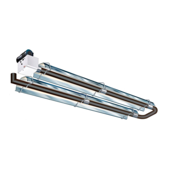
- Page 1 INSTALLATION / OPERATION / MAINTENANCE Model VPS 120V 60Hz Applies to: Gas-Fired, Tubular, Radiant, Low-Intensity Infrared Heater Model VPS Burner/Control Box with 20 - 80 ft Tube/Reflector Length Form I-VPS (Version C) Part No. 270683...
-
Page 2: Table Of Contents
Introduction. Welcome to the new range of powered infra-red heaters specified in these instructions, due care heaters. Local regulations may vary and it is the and attention is required to ensure that working installer’s responsibility to ensure that such reg- at height regulations are adhered to. -
Page 3: Heater Suspension
installed in accordance with the Standard for Parking Structures, ANSI/NFPA 88A, They must be adequately fixed and designed to or the Standard for Repair Garages, carry the whole weight of the heater. In the event suitable roof steelwork being ANSI/NFPA 88B, Canadian unavailable, additional steelwork should be fitted... -
Page 4: Clearance To Combustibles
ON U TUBE VARIANTS THE HEATER SHOULD SLOPE DOWNWARDS TOWARDS THE RETURN BEND AND ON LINEAR VARIANTS SHOULD SLOPE DOWNWARDS TOWARDS BURNER BY APPROX. ½” FOR HORIZONTAL INSTALLATIONS AS SHOWN BELOW (DIAGRAMS EXAGGERATED FOR CLARITY) 1/2” 1/2” Outlet U bend U Tube heater side view Linear heater side view Clearance to Combustibles. - Page 5 Figure 2 Clearance to Combustibles. The minimum clearances to combustible materials are given in the tables below. These minimum distances MUST be adhered to at all times. Adequate clearance MUST be provided around air openings into the combustion chamber and there MUST be suitable clearance for accessibility and for combustion / ventilating air supplies.
- Page 6 Figure 3. Correct orientation of Ball Valve Gas Connection and Supply WARNING: Before installation, check that the local distribution conditions, nature of gas and pressure, and adjustment of the appliance are compatible. Gas Flow The gas connection on the heater is ½” N.P.T internal thread.
-
Page 7: Electrical Connections
* Connector must be certified for use on a radiant tube type infrared heater and must comply with Standard for Table 3 Connectors for Gas Appliances, ANSI Z21.24/CSA 6.10 or with the Standard for Elastomeric Composite Hose and HOSE SIZE CANADA Hose Couplings for Conducting Propane and Natural Gas, CAN/CGA 8.1. - Page 8 Figure 5a. Single and Multiple Heater Installations 120V Control KEY: G-GREEN 120V 60Hz 1 Ph W-WHITE Supply circuit BK-BLACK L1 (HOT) 110V Thermostat 120V Thermostat Other burners Burner 1 other burners Figure 5b. Single Heater Installations 24V Control METHOD:- Cut and strip pink cables linking terminals W1 and R KEY: Attach thermostat wires using suitable wire nuts.
- Page 9 Figure 6. Internal Burner Wiring Diagram. 120V AC Fan 120V/60Hz AC Supply KEY: BL - BLUE BK - BLACK BR - BROWN GR - GREY G - GREEN K - PINK R - RED W - WHITE Y - YELLOW 120v/24VAC 60Hz Power ON (red) Pressure Switch...
-
Page 10: Unvented Units
This protects building material from 1.6 Vent Requirements and Details degradation by the vent gasses. 1.6.1 Unvented units Vent joints should be sealed and secured according vent manufacturers Heaters may be installed without a vent instructions. Should condensation occur the providing the governing building codes are met vent should be shortened or insulated. - Page 11 Figure 7.a Vertical Venting. CODE APPROVED VENT THROUGH ROOF ROOF SEAL APPROVED CAT III VENT PIPE ALUMINUM 4" (101mm) O.D. OR 6" (152mm) O.D. FLUE 12'-0" (3.66m) 12'-0" (3.66m) SEAL JOINTS WITH (APPROXIMATE HIGH TEMPERATURE SILICONE MAXIMUM DIMENSIONS) 4" (101mm) TO 6" (152mm) DIA. ALUMINUM ADAPTER CAT III ADAPTER REQUIRED ONLY FOR 6"...
-
Page 12: Technical Details
Technical Details - Table 5 No of Injectors ½” N.P.T Gas Connection 120 volt 1 phase 60Hz Electrical Supply 4” or 6” (101mm or 152mm) Vent size (in) 120 volt 1 phase 60Hz Unitary Fan Motor Details 1.2A MAX Current Rating Electronic Program Start up with Spark Ignition Ignition Min. - Page 13 Technical Details continued USA & CANADA Natural Gas 0- 2000 ft (0-610m) Size Burner Orifice Plate 269954 269955 269943 269944 269945 269946 269946 Part No. 270476 270475 Fan Type Fan Orifice 269923 269922 269923 269927 269926 266930 269938 Part No. Injector 270400 270402 270404 270406 270408 270409 270410 Part No.
- Page 14 Technical Details continued U Tube Straight Tube MODEL ● ● ● ● ● ● ● ● ● ● ● ● ● ● ● ● ● ● ● ● ● ● ● ● ● ● ● ● ● ● ● ● ●...
-
Page 15: Assembly Instructions
2. Assembly Instructions. PLEASE READ this section prior to Please ensure that all packaging is assembly to familiarize yourself with the disposed of in a safe environmentally components and tools you require at the friendly way. various stages of assembly. Carefully open the packaging and check the contents against the For your own safety we recommend the parts and check list. -
Page 16: Couplers
Type ‘F’ are fixed reflector brackets. 2.2.4 Couplers The couplers are used for joining radiant tubes and U or L bends. Slide the coupler over the tube ensuring that the screw stop has butted up to the tube ends. Using the 9/16”... -
Page 17: End Caps (Optional
REFLECTORS BURNER ASSEMBLY Typical usage of optional bend kits: 90° Elbow Corner reflector 90° Bend End Caps End Cap 2.2.6 End Caps (optional) Corner reflectors (optional) Corner reflectors kit Position an end cap beneath the reflector profile (where required) with the end cap flanges facing inwards. - Page 19 Figure 9. Heater Assembly: Model Linear 60-S20 and 80-S20.
- Page 20 Figure 10. Heater Assembly: Model Linear 60-S30, 80-S30 and 100-S30.
- Page 21 Figure 11. Heater Assembly: Model Linear 60-S40, 80-S40, 100-S40, 125-S40 and 150-S40.
- Page 22 Figure 12. Heater Assembly: Model Linear 100-S50, 125-S50, 150-S50, 170-S50, and 200-S50...
- Page 23 Figure 13. Heater Assembly: Model Linear 125-S60, 150-S60, 170-S60 and 200-S60...
- Page 24 Figure 14. Heater Assembly: Model Linear 150-S70, 170-S70 and 200-S70.
- Page 25 Figure 15. Heater Assembly: Model Linear 170-S80 and 200-S80...
- Page 26 Figure 16. Heater Assembly: Model U tube 60-U20 and 80-U20. 3' 3"...
- Page 27 Figure 17. Heater Assembly: Model U tube 60-U40, 80-U40, 100-U40, 125-U40 and 150-U40. 3' 3"...
- Page 28 Figure 18. Heater Assembly: Model U tube 125-U60, 150-U60, 170-U60 and 200-U60 3' 3"...
- Page 29 Figure 19. Heater Assembly: Model U tube 170-U80 and 200-U80 3' 3"...
-
Page 30: Tools Required
3. Start Up Instructions. These appliances should be commissioned by a qualified mechanical contractor. Tools Required. The following tools and equipment are advisable Suitable alternative tools may be used. to complete the tasks laid out in this manual. Large Adjustable Small Flat Leather Phillips... - Page 31 Start heater using suitable screwdriver adjust the pressure regulator, turning the screw clockwise to increase the pressure or counter-clockwise to decrease the pressure. Set the pressure to appropriate inches w.c. from the table of gas pressures and orifice plate dimensions for correct heater description. Switch off the power supply to the heating system.
-
Page 32: Servicing Instructions
Commissioning chart Check installation has Ensure gas and electricity Disconnect gas hose from been carried out to these supplies are isolated. burner instructions. Remove burner from tube and inspect burner head. (See servicing instructions) Reconnect gas hose. Open control housing and Replace burner on tube Open manual valve. -
Page 33: Burner Description
4. Servicing Instructions. These appliances should be serviced annually by a competent person to ensure safe and efficient operation. In mildly dusty or polluted conditions more frequent servicing may be required. Servicing work should be carried out by a qualified mechanical contractor. -
Page 34: Burner Removal
in a safe area to prevent the burner or 4.3 Burner Removal components attached to the burner from falling Step 1: Isolate power and gas supplies. to the ground. Step 2: Unplug the power connectors. 4.4 Burner Gas Injector Servicing Step 1.a: Remove the burner support casting Step 3: Detach the gas supply as shown be- and gasket. -
Page 35: Burner Head And Electrode Servicing
the two screws and separating the igniter lead connectors. Step 3: Reconnect ignition leads, ground lead and silicone tube to test nipple. Refit gasket and support casting. Step 4: Refit the electrode assembly and en- sure the connections are secure to prevent in- 4.5 Burner Head and Electrode Servicing correct sparking . -
Page 36: Radiant Tube Servicing
Step 2: Remove fan retaining screws and unplug from burner box. 4.8 Reflector Servicing The condition of the reflectors should be noted. If necessary the reflectors can be cleaned with a mild detergent. This can significantly improve the efficiency of the appliance. -
Page 37: Spare Parts
5. Spare Parts. Required Spares Note: Any spare part components that are In order to aid troubleshooting and servicing we not approved by the manufacturer could recommend that the components shown in this invalidate the approval of the appliance and the section should be stocked. -
Page 38: Troubleshooting Guide
6. Troubleshooting Guide. START Ensure gas & electricity supplies are enabled. Turn any external timer to call for heat (if fitted). CHECK: - Does the Power On Is there power to the 1. Transformer light illuminate? burner? 2. Integrity of wiring connections. 3. - Page 39 To aid the troubleshooting process, the UT controller has a LED flash code diagnostic se- quence: Steady Off No control power Steady On Power applied, control OK Combustion pressure switch open with blower on 1 Flash Combustion pressure switch closed with blower off 2 Flashes Lockout from the three ignition trials 3 Flashes...
-
Page 40: Replacing Parts
7. Replacing Parts. 7.2 Air Pressure Switch Replacement Turn off gas and any electrical supplies to the heater before starting repair work. Step 1: Open left hand door. Disconnect the two silicone tubes from the pressure switch. 7.1 Burner Controller Replacement Step 1: Loosen screw in right hand burner access door and open. -
Page 41: Gas Valve Replacement
7.3 Gas Valve Replacement Step 6: Detach the two screws securing the front of the gas valve. Step 1: Remove the burner assembly as described in the servicing section. Step 2: Open the right hand access door and detach the burner controller from the wiring harness. -
Page 42: Optional Extra Kits
7.4 Optional Extra Kits. - Page 43 Notes.
-
Page 44: User And Operating Instructions
800-695-1901 www.RezSpec.com ©2014 Reznor, LLC. All rights reserved. Trademark note: Reznor is registered in at least the United States. All other marks are the property of their respective organizations. 0114 Form I-VPS ( Version C.1)
Need help?
Do you have a question about the VPS and is the answer not in the manual?
Questions and answers