
Related Manuals for Beckhoff ELX Series


Summary of Contents for Beckhoff ELX Series
- Page 1 Documentation Control Drawing ELX Connection diagrams, EX markings and technical data for explosion protection Version: Date: 2019-08-27...
-
Page 3: Table Of Contents
Table of contents Table of contents 1 Foreword .............................. 5 Notes on the documentation...................... 5 Safety instructions .......................... 6 Documentation issue status ...................... 7 2 Connection diagramms.......................... 8 Terminals with digital inputs ...................... 8 2.1.1 ELX1052 .......................... 8 2.1.2 ELX1054 .......................... 9 Terminals with digital outputs ...................... 10 2.2.1 ELX2002 .......................... - Page 4 Table of contents Version: 0.4 Control Drawing ELX...
-
Page 5: Foreword
EP1590927, EP1789857, EP1456722, EP2137893, DE102015105702 with corresponding applications or registrations in various other countries. ® EtherCAT is registered trademark and patented technology, licensed by Beckhoff Automation GmbH, Germany. Copyright © Beckhoff Automation GmbH & Co. KG, Germany. The reproduction, distribution and utilization of this document as well as the communication of its contents to others without express authorization are prohibited. -
Page 6: Safety Instructions
All the components are supplied in particular hardware and software configurations appropriate for the application. Modifications to hardware or software configurations other than those described in the documentation are not permitted, and nullify the liability of Beckhoff Automation GmbH & Co. KG. Personnel qualification This description is only intended for trained specialists in control, automation and drive engineering who are familiar with the applicable national standards. -
Page 7: Documentation Issue Status
Foreword Documentation issue status Version Comment • Chapter Ex Marking added • Chapter Specific condition of use added • Technical data for explosion protection extended • Technical data for explosion protection corrected • First preliminary version Control Drawing ELX Version: 0.4... -
Page 8: Connection Diagramms
Connection diagramms Connection diagramms Terminals with digital inputs 2.1.1 ELX1052 Two-channel digital input terminals for NAMUR sensors, Ex i Fig. 1: ELX1052 - Sensor connection Version: 0.4 Control Drawing ELX... -
Page 9: Elx1054
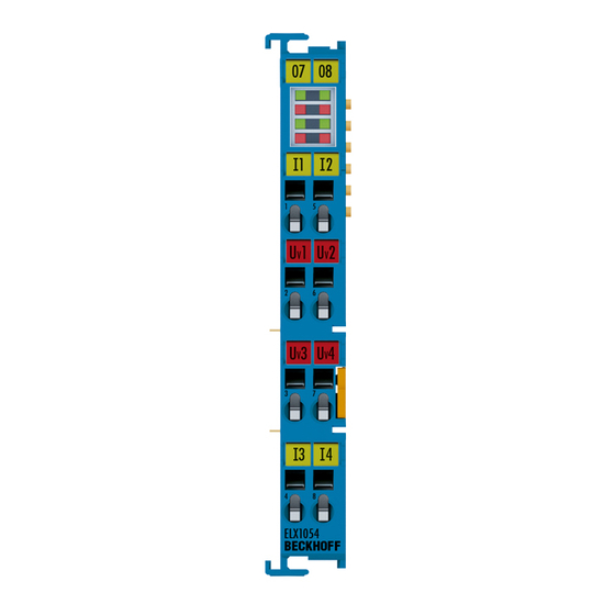
Connection diagramms 2.1.2 ELX1054 Four-channel digital input terminals for NAMUR sensors, Ex i Fig. 2: ELX1054 - Sensor connection Control Drawing ELX Version: 0.4... -
Page 10: Terminals With Digital Outputs
Connection diagramms Terminals with digital outputs 2.2.1 ELX2002 Two channel, digital output terminal, 24 V , 40 mA, Ex i Fig. 3: ELX2002 - Actuator connection Version: 0.4 Control Drawing ELX... -
Page 11: Terminals With Analog Inputs
Connection diagramms Terminals with analog inputs 2.3.1 ELX3152 Two channel, analog, output terminal, 0/4…20 mA, single-ended, 16 Bit, Ex i 2-wire Fig. 4: ELX3152 - Sensor connection (2-wire) Control Drawing ELX Version: 0.4... - Page 12 Connection diagramms 4-wire Fig. 5: ELX3152 - Sensor connection (4-wire) Version: 0.4 Control Drawing ELX...
-
Page 13: Elx3181
Connection diagramms 2.3.2 ELX3181 One-channel analog input terminal 4…20 mA, single-ended, 16 bit, HART, Ex i Fig. 6: ELX3181 - Sensor connection Control Drawing ELX Version: 0.4... -
Page 14: Elx3202
Connection diagramms 2.3.3 ELX3202 Two-channel analog input terminal, RTD, 16 bit, Ex i 2-wire Fig. 7: ELX3202 - Sensor connection (2-wire) Version: 0.4 Control Drawing ELX... - Page 15 Connection diagramms 3-wire Fig. 8: ELX3202 - Sensor connection (3-wire) Control Drawing ELX Version: 0.4...
- Page 16 Connection diagramms 4-wire Fig. 9: ELX3202 - Sensor connection (4-wire) Version: 0.4 Control Drawing ELX...
-
Page 17: Elx3204
Connection diagramms 2.3.4 ELX3204 Four-channel analog input terminal, RTD, 16 bit, Ex i Fig. 10: ELX3204 - Sensor connection Control Drawing ELX Version: 0.4... -
Page 18: Elx3312
Connection diagramms 2.3.5 ELX3312 Two-channel analog input terminal for thermocouples, 16 bit, Ex i Fig. 11: ELX3312 - Connection of thermocouples Version: 0.4 Control Drawing ELX... -
Page 19: Elx3314
Connection diagramms 2.3.6 ELX3314 Four-channel analog input terminal for thermocouples, 16 bit, Ex i Fig. 12: ELX3314 - Connection of thermocouples Control Drawing ELX Version: 0.4... -
Page 20: Elx3351
Connection diagramms 2.3.7 ELX3351 One-channel analog input terminal for strain gauge, 16 bit, Ex i 4-wire Fig. 13: ELX3351 - Connection of strain gauge (4-wire) Version: 0.4 Control Drawing ELX... - Page 21 Connection diagramms 6-wire Fig. 14: ELX3351 - Connection of strain gauge (6-wire) Control Drawing ELX Version: 0.4...
-
Page 22: Terminals With Analog Outputs
Connection diagramms Terminals with analog outputs 2.4.1 ELX4181 One-channel analog output terminal 0/4…20 mA, single-ended, HART, 16 bit, Ex i Fig. 15: ELX4181 - Actuator connection Version: 0.4 Control Drawing ELX... -
Page 23: Terminals For Position Measurement
Connection diagramms Terminals for position measurement 2.5.1 ELX5151 One-channel incremental encoder interface, NAMUR, 32 bit, Ex i Fig. 16: ELX5151 - Connection of incremental encoder Control Drawing ELX Version: 0.4... -
Page 24: Ex Markings
Ex Markings Ex Markings Ex Markings on ELX signal terminals Fig. 17: ELX2008-0000 with date code 2519HMHM, BTN 0001f6hd and Ex marking The Ex marking in this Figure is identical on all ELX signal terminals, that includes ELX1052, ELX1054, ELX2002, ELX2008, ELX3152, ELX3181, ELX3202, ELX3204, ELX3312, ELX3314, ELX3351, ELX4181 and ELX5151. - Page 25 Ex Markings Ex Markings on ELX power supply terminals Fig. 18: ELX9560-0000 with date code 12150000, BTN 000b000 and Ex marking. The Ex marking in this figure is identical on ELX9410 and ELX9560. Control Drawing ELX Version: 0.4...
- Page 26 Ex Markings Ex Markings on ELX bus end cover Fig. 19: ELX9012 with date code 12174444, BTN 0000b0si and Ex marking Version: 0.4 Control Drawing ELX...
-
Page 27: Technical Data For Explosion Protection
[} 23] C, E 10.72 12.4 D, F, G NOTE Installation, parameterization, programming etc. Further information on installation, parameterization, programming etc. can be found in the respective terminal-specific documentation, which is available for download on https://www.beckhoff.de/english/download/ethercat.htm. Control Drawing ELX Version: 0.4... -
Page 28: Appendix
• The last terminal of each segment is to be covered by a bus end cover ELX9012, unless two ELX9410 terminals are installed in direct succession for continuing the same terminal segment with standard Beckhoff EtherCAT terminals (e.g. EL/ES/EK). • An additional ELX9560 power supply terminal, followed by further ELX signal terminals can be con- nected to the right side of the ELX9410. -
Page 29: Support And Service
Beckhoff's branch offices and representatives Please contact your Beckhoff branch office or representative for local support and service on Beckhoff products! The addresses of Beckhoff's branch offices and representatives round the world can be found on her internet pages: http://www.beckhoff.com You will also find further documentation for Beckhoff components there.
Need help?
Do you have a question about the ELX Series and is the answer not in the manual?
Questions and answers