Advertisement
Table of Contents
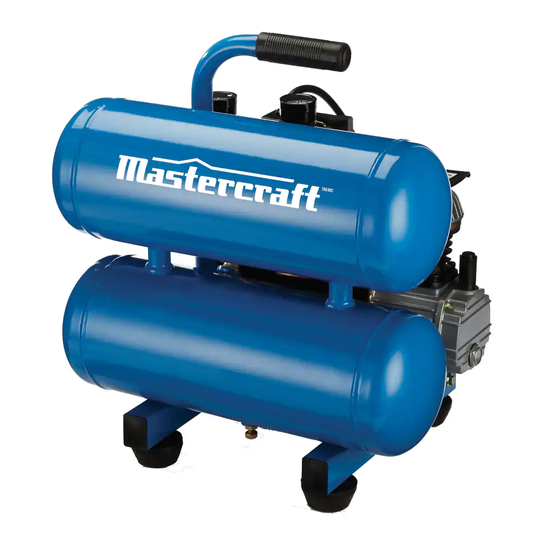
- 1 Air Compressor
- 2 Table of Contents
- 3 Quick Start Guide
- 4 Overview
- 5 Safety Guidelines
- 6 Compressor Controls
- 7 Assembly
- 8 Electrical Power Requirements
- 9 Break-In of the Pump
- 10 Operating Instructions
- 11 Maintenance
- 12 Troubleshooting
- 13 Bs Exploded View & Parts List
- 14 Parts & Service
- 15 Warranty
- 16 Additional Limitations
- Download this manual
Advertisement
Table of Contents

Related Manuals for MasterCraft 299-3117-6


Summary of Contents for MasterCraft 299-3117-6
-
Page 1: Air Compressor
299-3117-6 Premium Submersible AIR COMPRESSOR SUMP PUMP Product style and configuration may vary. IMPORTANT: INSTRUCTION Please read this manual carefully before running this MANUAL air compressor and save it for reference. - Page 2 headline bars headline bars continuation tabs notes continuation tabs warnings notes warnings...
-
Page 3: Table Of Contents
TABLE OF CONTENTS Quick Start Guide Overview Safety Guidelines Compressor Controls Assembly Electrical Power Requirements Break-In of the Pump Operating Instructions Maintenance Troubleshooting Exploded View & Parts List Parts & Service Warranty NOTE: If any parts are missing or damaged, or if you have any questions, please call our toll-free helpline at 1-800-689-9928. -
Page 4: Quick Start Guide
299-3117-6 | contact us 1-800-689-9928 STEP 1 Place the compressor on the floor or a hard, level surface in a clean, continuation tabs continuation tabs well-ventilated area. notes notes STEP 2 Connect the air hose (1) between the... - Page 5 STEP 3 Make sure the AUTO/OFF switch (1) is in OFF position and drain valve at the bottom of tank is closed. STEP 4 Turn the pressure regulator knob (1) counterclockwise completely. Plug the power cord (2) into electrical outlet. Turn the AUTO/OFF switch (3) to the AUTO position.
-
Page 6: Overview
299-3117-6 | contact us 1-800-689-9928 BASIC AIR COMPRESSOR COMPONENTS • The basic components of the air compressor are the electric motor, pump, pressure switch, and tank. • The electric motor (A, Fig. 1) powers the pump. The electric motor is equipped with an overload protector. -
Page 7: Safety Guidelines
SAFETY GUIDELINES Please read this before operating the compressor. This information is provided for your SAFETY and to PREVENT EQUIPMENT PROBLEMS. Most accidents can be avoided by using COMMON SENSE. Do not wear loose clothing that may become entangled in the impeller or other moving parts. WARNING •... - Page 8 299-3117-6 | contact us 1-800-689-9928 SAFETY GUIDELINES • RISK OF BURNS. High temperatures are generated by the pump and manifold. To prevent burns or other injuries, DO NOT touch the pump, manifold or transfer tube while the pump is running.
- Page 9 RISK OF ELECTRICAL SHOCK. Never use an electric air compressor outdoors when it is raining or on a wet surface, as it may cause an electric shock. PUMP SHIPPED WITHOUT OIL. Fill pump to correct mark and check often. SAE-30 non-detergent oil is recommended for general use. CAUTION •...
-
Page 10: Compressor Controls
299-3117-6 | contact us 1-800-689-9928 CONTROLLING THE COMPRESSOR PRESSURE SWITCH (A, Fig. 2) • This switch turns on the compressor. It is operated manually, but when in the ON position, it allows the compressor to start up or shut down automatically, without warning, upon air demand. -
Page 11: Assembly
ASSEMBLING THE COMPRESSOR PUMP SHIPPED WITHOUT OIL. Fill pump to correct mark and check often. SAE-30 non-detergent oil is recommended for general use. • Unpack the air compressor. Inspect the unit for damage. If the unit has been damaged in transit, contact the carrier and complete a damage claim. Do this immediately because there are time limitations to damage claims. -
Page 12: Electrical Power Requirements
299-3117-6 | contact us 1-800-689-9928 ELECTRICAL WIRING Refer to the air compressor’s serial label for the unit’s voltage and amperage requirements. USE A DEDICATED CIRCUIT • continuation tabs continuation tabs For best performance and reliable starting, the air compressor must be plugged into a dedicated circuit, as close as possible to the fusebox or circuit breaker. - Page 13 GROUNDING INSTRUCTIONS (CONTINUED) • Improper installation of the grounding plug can result in a risk of electric shock. If repair or replacement of the cord or plug is necessary, do not connect the grounding wire to either flat blade terminal. The wire insulation having an outer surface that is green with or without yellow stripes is the grounding wire.
-
Page 14: Break-In Of The Pump
299-3117-6 | contact us 1-800-689-9928 BREAK-IN OF THE PUMP PUMP SHIPPED WITHOUT OIL. Fill pump to correct mark and check often. SAE-30 non-detergent oil is recommended for general use. • Check the level of oil in the pump with the sight glass. The pump oil level must be between A and B (see Fig. -
Page 15: Operating Instructions
DAILY STARTUP • Every day check the sight glass to ensure that the level of oil in the pump is at the required level. The pump oil level must be between A and B (see Fig. 6). Do not overfill or underfill. •... -
Page 16: Maintenance
299-3117-6 | contact us 1-800-689-9928 MAINTENANCE WARNING:To avoid personal injury, always shut off and unplug the compressor and relieve all air pressure from the system before performing any service on the air compressor. •... - Page 17 TESTING FOR LEAKS • Check that all connections are tight. A small leak in any of the hoses, transfer tubes, or pipe connections will substantially reduce the performance of your air compressor. If you suspect a leak, spray a small amount of soapy water around the area of the suspected leak with a spray bottle.
-
Page 18: Troubleshooting
299-3117-6 | contact us 1-800-689-9928 TROUBLESHOOTING Problem Possible Causes Solution Low pressure or not Tank drain valve is open Close drain valve. enough air Fittings leak Check fittings with soapy water. Tighten or reseal leaking fittings. DO NOT Compressor does OVERTIGHTEN. - Page 19 TROUBLESHOOTING Problem Possible Causes Solution Motor stalls Low voltage Furnish adequate power. Defective pressure switch Replace pressure switch bleeder valve. bleeder valve Pressure relief Tank pressure exceeded normal Replace pressure switch. valve opens operating pressure Pressure switch stuck Replace pressure switch. Motor will not run Tank pressure exceeds preset Motor will start automatically when...
-
Page 20: Bs Exploded View & Parts List
299-3117-6 | contact us 1-800-689-9928 PARTS LIST Description Qty. Description Qty. Shroud kit Nipple, Screw, M5 x 1/4” NPT x 3” .8 x 10 mm Regulator Pump/motor Tube, exhaust continuation tabs continuation tabs Assembly... - Page 21 PARTS LIST AVAILABLE SERVICE KITS Includes items Description Qty. E100434 36, 37, 38 Oil sight glass Oil sight glass seal E101402 16, 17, 19 Crankcase cover E101403 20, 30, 31 Oil fill cap E101332 50, 52, 53, 54, 55 E100959 39, 42, 43, 45, 50 E100251...
- Page 22 299-3117-6 | contact us 1-800-689-9928 continuation tabs continuation tabs notes notes warnings warnings...
-
Page 23: Parts & Service
PARTS AND SERVICE Replacement parts and service are available from your nearest authorized service centre. If the need arises, contact Product Service as listed. When consulting with a service centre or Product Service, refer to the model number and serial number located on the serial label of the compressor. Proof of purchase is required for all transactions and a copy of your sales receipt may be requested. -
Page 24: Warranty
299-3117-6 | contact us 1-800-689-9928 LIMITED WARRANTY 3-Year Limited Warranty This Mastercraft product is guaranteed for a period of 3 years from the date of original retail purchase against defects in workmanship and materials, except for the following component:... -
Page 25: Additional Limitations
This product is not meant for industrial or commercial purposes. This product is for household projects. Made in China Imported by Mastercraft Canada Toronto, Canada M4S 2B8...
Need help?
Do you have a question about the 299-3117-6 and is the answer not in the manual?
Questions and answers