Table of Contents
Advertisement
Advertisement
Table of Contents

Related Manuals for MasterCraft 099-4119-2


Summary of Contents for MasterCraft 099-4119-2
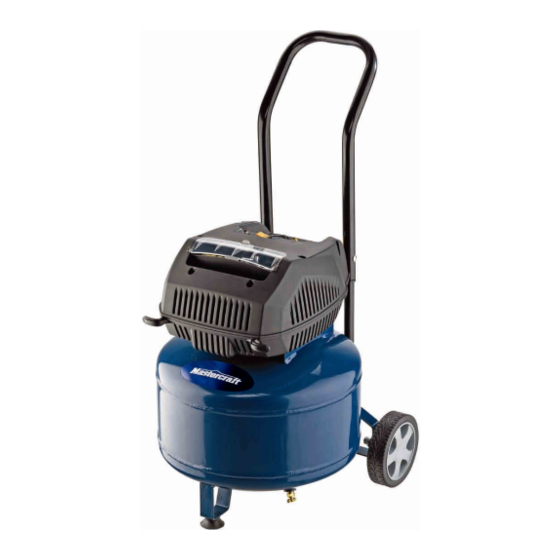
- Page 1 Owner's Manual 8 GALLON AIR COMPRESSOR 099-4119-2 1-877-888-3872 TOLL FREE HELPLINE: CAUTION : Before using this tool or any of its accessories, read this manual and follow all Safety Rules and Operating Instructions. Imported by Mastercraft Canada, Toronto, Canada M4S 2B8...
-
Page 2: Table Of Contents
TABLE OF CONTENTS SPECIFICATIONS..................... SAFETY GUIDELINES ..................IMPORTANT SAFETY INSTRUCTIONS ............3 GENERAL SAFETY RULES................ 9-10 SPECIFIC SAFETY RULES................11 GLOSSARY OF TERMS................. ACCESSORIES INCLUDED................. 13 ASSEMBLY....................14-22 MAINTENANCE ..................22-23 STORAGE ...................... 23 TROUBLESHOOTING................24-26 LIMITED WARRANTY ..................27 EXPLODED VIEW/PARTS LIST.............. -
Page 3: Safety Guidelines
SAFETY GUIDELINES - DEFINITIONS This manual contains information that is important for you to know andunderstand. This information relates to protecting YOUR SAFETY and PREVENTING EQUIPMENT PROBLEMS. To help you recognize thisinformation, we use the symbols below. Please read the manual and payattention to these symbols. Indicates animminently Indicates apotentially hazardoussituation which, if not avoided,... - Page 4 IMPORTANT SAFETY INSTRUCTIONS Save these instructions Improper operation or maintenance of this product could result in serious injury andproperty damage. Read and understand all warnings and operating instructions before using this equipment. HAZARD WARNING: Risk of explosion or fire What Could Happen How To Prevent It It is normal for electrical contacts within Always operate the compressor in a...
- Page 5 WARNING: Risk of Bursting Air Tank: The following conditions could lead to a weakening of the tank, and result in a violent tank explosion and could cause property damage or serious injury. What Could Happen How To Prevent It 1. Failure to properly drain condensed water Drain tank daily or after each use.
- Page 6 HAZARD WARNING: Risk of Electric Shock What Could Happen How To Prevent It Your air compressor is powered by Never operate the compressor outdoors electricity. Like any other electrically when it is raining or in wet conditions. powered device, it may cause electric Never operate the compressor with shock if it is not used properly.
- Page 7 What Could Happen How To Prevent It Touching exposed metal such as the Never touch any exposed metal parts compressor head or outlet tubes can on the compressor during or immediately result in serious burns. after operation. Compressor will remain hot for several minutes after operation.
- Page 8 WARNING: RISK OF SERIOUS INJURY OR PROPERTY DAMAGE WHEN TRANSPORTING COMPRESSOR (Fire, Inhalation, Damage to Vehicle Surfaces) What Could Happen How To Prevent It Oil can leak or spill, which could cause a Always place the COMPRESSOR on a fire or breathing hazard resulting in protective mat when transporting in order serious injury or death.
-
Page 9: General Safety Rules
GENERAL SAFETY RULES WORK AREA Keep your work area clean and well lit. Cluttered benches and dark areas invite accidents. Do not operate power tools in an explosive atmosphere, such as in the presence of flammable liquids, gases, or dust. Power tools create sparks that may ignite dust or fumes. - Page 10 GENERAL SAFETY RULES Avoid accidental start-ups. be sure the power switch is off before plugging in the tool. Carrying a power tool with your finger on the power switch or plugging in a power tool with the power switch on invites accidents. Remove adjusting keys or wrenches before turning the power tool on.
-
Page 11: Specific Safety Rules
SPECIFIC SAFETY RULES Maintain labels and nameplates on the Air Compressor. They carry important information. If unreadable or missing, contact the Toll-free Helpline, at 1-877-888-3872 for a replacement. Always wear ANSI-approved safety impact eye goggles and heavy work gloves when using the Air Compressor. Using personal safety devices reduces the risk of injury. -
Page 12: Glossary Of Terms
GLOSSARY OF TERMS Become familiar with these terms before operating the unit. CFM: Cubic feet per minute. SCFM: Standard cubic feet per minute; a unit of measure of air delivery. PSI: Pounds per square inch ; a unit of measure of pressure. Cut-In Pressure: While the motor is off, air tank pressure drops as you continue to use your accessory. -
Page 13: Accessories Included
ACCESSORIES INCLUDED The unit is supplied with an accessory kit and inflator/deflator kit. Choose the accessory needed. A-10 A-12 A-11 NAME ITEM AMOUNT MODEL NUM. Recoil air hose 3790175 Inflation needle 37902110 Rubber inflation nozzle 37906110 Tapered inflation nozzle 37904110 Blow gun adaptor fitting 37911110 Blow gun safety nozzle... - Page 14 ASSEMBLY Accessories The unit is supplied with an accessory kit and inflator/deflator kit. Choose the accessory needed. Installing Accessories (See Fig. A) Installing the Tire Chuck 1. Attach the tire chuck (a) to the hose (b), and tighten securely using wrenches. Installing Accessories 1.
- Page 15 ASSEMBLY Installing the Inflation Needle or the Tapered Inflation Nozzle The blow gun (c) and blow gun adaptor (e) from the accessory kit are required in order to use the inflator/deflator kit. (See Fig. B/Fig. C) 1. Attach the blow gun to the hose. 2.
-
Page 16: Assembly
ASSEMBLY Quick-Connect (See Fig. D) 1. Assemble the 1/4”male quick-connec t plug (k,l) or 1/4” female quick-connect plug to the 1/4” Female quick-connect body. 2. Attach the quick-connect plug to the hose. PULL Fig. D NOTE: Always use PTFE tape on all threaded components, to prevent leaks. -
Page 17: Assembling The Compressor
ASSEMBLY Precautions Drain the moisture from the tank daily to help prevent corrosion. Pull the pressure relief valve ring daily to ensure proper function and clear possible obstructions. To provide proper ventilation for cooling, the compressor must be kept at least 12” (31 cm) from the nearest wall, in a well-ventilated area. - Page 18 ASSEMBLY Mini Die Grinder Disconnect air tool from air supply before changing attachments orserious injury could occur. WARNING 1.Insert stem of grinder attachmentinto collet opening (See Fig. F ). Make sure stem is fully inserted. 2.Securely tighten collet withwrenches (supplied with somemodels) (See Fig. G & H ). Apply one wrench to the collet nutand the other to the spindle.
- Page 19 Compatible Compressors: Guidelines for Proper Use and Operation Be sure to use the proper air compressor with Mastercraft® air-powered tools. The compressor that is being used must be able to supply the proper amount of pressure (PSI) to the tool. Verify that the tool does not require more SCFM (Standard Cubic Feet per Minute) than the compressor can deliver without running continuously.
-
Page 20: Electrical Power Requirements
ASSEMBLY Compressor Controls Fig J Pressure switch: This switch turns the compressor ON. It can be operated manually, but when in the ON position, it allows the compress or to start up or shut down automatically, without warning, on demand. ALWAYS set this switch to OFF Pressure Relief Valve: If the pressure switch does not shut down the motor when the pressure reaches the preset level, this valve will pop open automatically to prevent over-pressurization. -
Page 21: Extension Cord
Note: A circuit breaker is recommended. If the air compressor is connected to a circuit protected by a fuse, use dual element time delay fuses (Buss Fusetron type “1” only). Extension Cord Note: Avoid use of extension cords. For optimum performance, plug the compressor power cord directly into a grounded wall socket. Do not use an extension cord unless absolutely necessary. -
Page 22: Maintenance
6. After about 15 minutes, turn the pressure switch to the OFF position. 7. Close the air pressure regulator by turning it clockwise. Turn the pressure switch to ON. The tank will now fill. Note: As compressed air is used, the pressure switch will restart the motor automatically. Note: During the initial break-in cycle, there will be a slight electrical smell as the motor brushes seat. -
Page 23: Storage
Draining the Tank Relieve the air pressure in the system and open the drain valve on the bottom of the tank to drain. WARNING! CONDEN SATION WILL ACCUMULATE IN THE TANK. TO PREVENT CORROSION OF THE TANK FROM THE INSIDE, THIS MOISTURE MUS T BE DRAINED AT THE END OF EVERY WORKDAY. -
Page 24: Troubleshooting
TROUBLESHOOTING Note: Troubleshooting problems may have similar causes and solutions. PROBLEM POSSIBLE CAUSE SOLUTION Low pressure - Close valve Tank Pressure Relief valve is open. Prolonged excessive use of air. Not enough air - Decrease use Compressor not large enough. Compressor - Check air requirement of accessory. - Page 25 Circuit breaker/ - Link additional air hoses together to • Excessive wire length causes fuse trips. Often acquire additional length; voltage to drop too much. DO NOT USE AN EXTENSION CORD - Contact authorized service centre. • Restricted air passages. - Replace check valve and/or pressure switch bleeder valve.
- Page 26 Check valve stuck open. - Bleed line by moving pressure switch lever to OFF position before restarting. Pressure bleeder valve on pressure If bleeder valve does not open, replace switch has not unloaded head bleeder valve. pressure. - Link additional air hoses together to acquire more length;...
-
Page 27: Limited Warranty
WARRANTY 3-Year Limited Repair Warranty This Mastercraft product is guaranteed for a period of 3 years from the date of original retail purchase against defects in workmanship and materials, except for the following component: Component A: Accessories, which are guaranteed for a period of 1-year from the date of original retail purchase against defects in workmanship and materials. -
Page 28: Exploded View/Parts List
Parts List Description Qty No Description 3220404 BOLT ST4.2×25-F 3750251-2 COPPER TIE-IN φ8.5[1/4,NPT] 3410483 STORAGE COVER 3390151 HANDLE 3630183-1 OVERLOAD PROTECTION 3220837 BOLT M8X45 3630283-3 POWER SWITCH 3410835 TURNCAP 3390251 CONNECTOR TUBE 34101119 UPPER COVER 34102119 LOWER COVER 31105119 MOTOR-PUMP ASSEMBLLY 3220450 BOLT M6×30 3110651-3...
Need help?
Do you have a question about the 099-4119-2 and is the answer not in the manual?
Questions and answers