Table of Contents

Subscribe to Our Youtube Channel
Related Manuals for ADC Soneplex D3LXC-FCA100

Summary of Contents for ADC Soneplex D3LXC-FCA100
- Page 1 Soneplex DS3 Loop Extender (D3LX) CO Module Product: D3LXC-FCA100, D3LXC-SCA100 CLEI Code: SOCPG2GB, SOCPG2KB Soneplex DS3 Loop Extender (D3LX) RMT Module Product: D3LXR-FCA100, D3LXR-SCA100 CLEI Code: SOCPG2HB, SOCPG2JB ANUAL...
- Page 2 Contents herein are current as of the date of publication. ADC reserves the right to change the contents without prior notice. In no event shall ADC be liable for any damages resulting from loss of data, loss of use, or loss of profits, and ADC further disclaims any and all liability for indirect, incidental, special, consequential or other similar damages.
-
Page 3: Using This Manual
Unpack each container and inspect the contents for signs of damage. If the equipment has been damaged in transit, immediately report the extent of damage to the transportation company and to ADC DSL Systems, Inc. Order replacement equipment, if necessary. - Page 4 Inspecting Shipment LTPS-UM-8013-03 August 30, 2002 D3LX CO and RMT Modules...
-
Page 5: Table Of Contents
LTPS-UM-8013-03 ABLE OF ONTENTS Overview ____________________________________________________________________________ 1 Front-Panel Description________________________________________________________________ 3 Protection Switching ...4 Automatic Switching ...5 Manual Switching...5 Applications ...5 Preparing to Install D3LX Modules ______________________________________________________ 6 Installing the BNC Panel _______________________________________________________________ 7 Overview ...7 Installation of the Panel...7 Installing a D3LX CO Module in an LEC _________________________________________________ 9 Power Verification ...12 Verification of Electrical DS3 Power Level...12 Verification of D3LX CO Optical Power...13... - Page 6 Table of Contents Performance Monitoring ... 29 Performing System Maintenance ... 30 Logging Off ... 31 Removing D3LX Modules ... 32 Remote Configuration ________________________________________________________________ 33 D3RCAM Menu ... 34 Unit Configuration... 34 Troubleshooting _____________________________________________________________________ 36 Appendix A - Specifications ____________________________________________________________ 37 D3LX Card-Edge Connector ...
- Page 7 1. D3LX CO and D3LX RMT Modules...1 2. System Overview...2 3. D3LX CO Front Panel...3 4. Mounting the BNC Panel and Connecting ADC Adapter Cables (LEC Shown)...8 5. Routing the Fiber Patch Cord ...10 6. D3LX Module Locations in Loop Extender Chassis...11 7.
- Page 8 List of Tables IST OF ABLES 1. D3LX Front-Panel Description and Status LEDs ... 4 2. Tip and Ring Assignments for Protection Switching Applications ... 8 3. Chassis Port Description ... 19 4. Navigational Keys for the Craft Interface Screens During Telnet Sessions ... 22 5.
-
Page 9: Overview
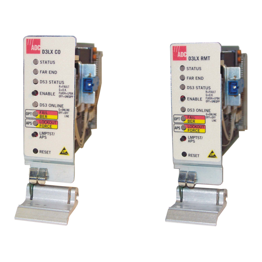
LTPS-UM-8013-03 VERVIEW ® The Soneplex DS3 Loop Extender (D3LX) modules shown in DS3 service. The D3LX CO resides at the Central Office (CO) site, and the D3LX RMT resides at the Customer Premises Equipment (CPE) or remote site. Figure 1. D3LX CO and D3LX RMT Modules The D3LX CO module occupies two card slots in a local, Soneplex Loop Extender Chassis (LEC). -
Page 10: System Overview
Overview DS3 out (transmit) BNC panel - front DS3 in (receive) D3LX CO STATUS FAR END DS3 STATUS R=FAULT G=O.K. ENABLE FLASH=LBK OFF=UNEQPP DS3 ONLINE G=ONLINE OFF=OFFLINE FAIL LOCKOUT FORCE LMPTST/ RESET Loop Extender - front D3LX CO DS3 in and out DS3 in and out AC/DC AC/DC... -
Page 11: Front-Panel Description
LTPS-UM-8013-03 RONT ANEL Figure 3 shows the D3LX CO front panel. components. For pinout diagrams of the D3LX card-edge connector, refer to page Automatic protection switching pushbutton D3LX CO and RMT Modules ESCRIPTION Table 1 on page 4 describes the LEDs and other front-panel D3LX CO STATUS FAR END... -
Page 12: Protection Switching
Front-Panel Description Table 1. D3LX Front-Panel Description and Status LEDs Name Function LEDs The LEDs can report the following conditions: Activity Color STATUS Not lit On (solid) Green On (solid) Yellow On (solid) FAR END Not lit On (solid) Yellow DS3 STATUS Off Not lit On (solid) -
Page 13: Automatic Switching
LTPS-UM-8013-03 Automatic Switching The 1:1 (Line) Protect mode transmits identical traffic across two parallel systems. The working and protect D3LX modules provide Automatic Protection Switching (APS) compatible with the remote D3LX module. APS is non-revertive and bidirectional and may be forced or disabled through the front-panel pushbuttons or the SCU software. -
Page 14: Preparing To Install D3Lx Modules
Cabinet or Two-Position QLX Remote BNC Chassis for the D3LX RMT). • a BNC Patch Panel with ADC adapter cables is installed in the CO rack and at the remote site. For more information about this operation, refer to •... -
Page 15: Installing The Bnc Panel
VERVIEW The ADC BNC Panel consists of 14 pairs of 75 BNC connectors that are part of a system that converts an electrical DS3 circuit at the CO site into an optical signal that uses WDM to transmit a signal across one single-mode fiber to a CPE site. -
Page 16: Mounting The Bnc Panel And Connecting Adc Adapter Cables (Lec Shown)
Installing the BNC Panel From the rear of the panel, connect the coax end of an ADC adapter cable to the DS3 OUT (transmit). connector. The connector number must match the connector number on the front of the panel. Connect the wire-wrap conversion block end of the same ADC adapter cable to the T and R EQUIP wire-wrap posts on the back of the LEC as shown in T1 and R1 LINE wire-wrap posts to prevent improper connection. -
Page 17: Installing A D3Lx Co Module In An Lec
When using D3LX CO modules in a group, never install other Soneplex modules in any of the unused slots in the same group. Remove any existing wire wraps from the LEC backplane prior to installing any ADC adapter cables (BNC-3-CBL-WW) for the groups that are being used for D3LX modules. -
Page 18: Routing The Fiber Patch Cord
Installing a D3LX CO Module in an LEC Fiber patch cord Locate the mounting slots designated for the D3LX CO modules in the chassis. Refer to Figure 6 on page 11 signal. – If no protection switching is required, proceed to the next step. –... -
Page 19: D3Lx Module Locations In Loop Extender Chassis
LTPS-UM-8013-03 D3LX CO D3LX CO STATUS STATUS FAR END FAR END DS3 STATUS DS3 STATUS R=FAULT R=FAULT G=O.K. G=O.K. ENABLE FLASH=LBK ENABLE FLASH=LBK OFF=UNEQPP OFF=UNEQPP DS3 ONLINE DS3 ONLINE G=ONLINE G=ONLINE R=LINELOCK R=LINELOCK FAIL OFF=OFFLINE FAIL OFF=OFFLINE LOCKOUT LOCKOUT FORCE FORCE LMPTST/ LMPTST/... -
Page 20: Power Verification
Installing a D3LX CO Module in an LEC Fiber clip After removing the protective cover from a fiber patch cord, clean the fiber-optic connector and adapter as directed in “Appendix B - Cleaning and Mating Fiber-Optic Systems” on page OWER ERIFICATION Verification of Electrical DS3 Power Level Apply power to the D3LX CO. -
Page 21: Verification Of D3Lx Co Optical Power
LTPS-UM-8013-03 Verification of D3LX CO Optical Power Connect an attenuator in series: • Connect a patch cord from the meter to the attenuator. • Connect a meter patch cord from the attenuator to the module. Using the retaining latch, press the module into the chassis until it is properly seated. Is the STATUS indicator lit green? •... -
Page 22: Power Verification
Installing a D3LX RMT Module in a Remote Cabinet D3LX RMT M NSTALLING A EMOTE ABINET Avoid exposure to invisible laser radiation. • Do not look into the ends of any optical fiber or directly into the module fiber connectors as exposure to invisible laser radiation may result. -
Page 23: D3Lx Rmt Module Locations In A Four-Position Remote Terminal Cabinet
LTPS-UM-8013-03 Locate the mounting slots designated for the D3LX RMT modules in the chassis. If protection switching is required, a working module installs in the first slot of a quad group, such as 1-1 or 2-1. The protection module installs in the slot to the right of the working module, slot 1-2 or 2-2. Refer to Figure 9 for D3LX RMT module locations chassis and slot corresponding to the DS3 signal. -
Page 24: Two-Position Qlx Remote Bnc Chassis Installation
Installing a D3LX RMT Module in a Remote Cabinet QLX R OSITION To install first the working module, and then the protect module (if installing D3LX RMT modules in protection switching applications): Open the front panel of the remote terminal into which the D3LX RMT will be installed. Route the fiber patch cord through the left side of the fiber management enclosure located on the remote terminal as shown in Figure... -
Page 25: Verification Of Optical Power
LTPS-UM-8013-03 Verification of Optical Power Connect an attenuator in series: • Connect a patch cord from the meter to the attenuator. • Connect a meter patch cord from the attenuator to the module. Using the retaining latch, press the module into the chassis until it is properly seated. Is the STATUS indicator lit green? •... -
Page 26: Provisioning
Provisioning Store the remaining slack fiber on the left side of the fiber management enclosure within the remote cabinet, leaving 5 to 6 inches of slack fiber above the upper card guide to provide a service loop. ROVISIONING In D3LX systems, provisioning occurs automatically if a remote module is installed. In the event that a remote module is not installed or properly functioning, refer to the manual provisioning process below. -
Page 27: Other Provisioning Considerations
LTPS-UM-8013-03 THER ROVISIONING Alarm Setting During Provisioning The D3LX generates alarms on conditions occurring in the D3LX CO modules DS3 facility. The severity of the alarm conditions as Critical, Major, Minor, or Event is selected while provisioning. The alarms are handed off to an Alarm Processing Unit (APU) which acts as an interface between the D3LX modules and the customer alarm monitoring equipment. -
Page 28: Connecting A Maintenance Terminal To The D3Rcam Craft Port
Setting Up System Options • 9600 baud • No parity • 8 data bits • 1 stop bit • Hardware flow control to OFF Figure 11. Connecting a Maintenance Terminal to the SCU The default port configuration for the SCU craft port is CRAFT. Ports 2 and 3 must be configured for CRAFT before the craft interface may be accessed via these ports. -
Page 29: Connecting A Maintenance Terminal To The D3Rcam
LTPS-UM-8013-03 At the maintenance terminal, press Figure 12. Connecting a Maintenance Terminal to the D3RCAM D3LX CO and RMT Modules . The Enter User Name field appears. ENTER Four-position remote terminal chassis Craft port August 30, 2002 Setting Up System Options Maintenance terminal Serial... -
Page 30: Navigating Through Craft Interface Menus
Setting Up System Options AVIGATING HROUGH Many of the operations that follow require the use of the craft interface. To select a menu from the craft interface, do one of the following: • Press the number of the menu. • Use the arrow keys to select the menu and press Table 4... -
Page 31: Local Configuration
LTPS-UM-8013-03 OCAL ONFIGURATION A D3LX system can be configured locally by an SCU (version 3.7 or later) with a D3LX CO module in an LEC. It can also be configured remotely by a D3RCAM with a D3LX RMT module installed in a remote chassis. See “Remote Configuration”... -
Page 32: D3Lx Co Configuration Fields–Scu V3.7 Or Later
Local Configuration Press for assistance when making selections. CTRL Configure the fields as detailed in the Repeat Steps 2 through 5 for each D3LX system installed in the chassis. Table 5. D3LX CO Configuration Fields–SCU V3.7 or later Field Name Type Unit Equip State Toggle... -
Page 33: Configuring D3Lx Alarms
LTPS-UM-8013-03 Table 5. D3LX CO Configuration Fields–SCU V3.7 or later (Continued) Field Name Type Housekeeping Labels Input Enter up to 8 1 and 2 alphanumeric characters. * This field shows as N/A if D3RCAM is not installed at the Four-Position Remote Terminal Cabinet or Two-Position QLX Remote BNC Chassis. -
Page 34: D3Lx Alarm Setting Menu
Local Configuration Equipment Alarms BOARD FAIL COMM FAIL CONFIG MISMATCH HSKP1, HSKP2 PROTECT COMM FAIL OPTICAL COMM FAIL VERSION MISMATCH Optical Facility Alarms APS LIMIT FORCE TO WORK FORCE TO PROT LASER DEGRADE OPTICAL LOF OPTICAL LOS T-BER DS3 Facility Alarm LOOPED BACK RECEIVE LOS TRANSMIT LOS... -
Page 35: Displaying D3Lx Status
LTPS-UM-8013-03 D3LX S ISPLAYING TATUS Use this procedure to display the status of both working and protect modules in local and remote sites. From the Main menu, select 2. Display Status. From the Alarms menu, select 5. Display D3LX Status (as shown in , and SPACEBAR D3LX CO and RMT Modules... -
Page 36: Viewing Loopback Status And Performing Loopback Commands
Local Configuration IEWING OOPBACK ERFORMING OOPBACK Use this procedure to view loopbacks and send loopback commands for a specific D3LX system. From the Main menu, select 6. System Maintenance. From the System Maintenance menu, select 4. Loopback Status Commands. From the Loopback Status/Commands menu, select 1. High/Low Speed Loopback Status/Commands (as shown in loopback tests for low-speed modules and their associated components. -
Page 37: Performance Monitoring
LTPS-UM-8013-03 ERFORMANCE ONITORING Use this procedure to monitor the performance of modules on both the near and far end of D3LX systems. From the Main menu, select 7. Performance Monitoring. From the Performance Monitoring menu, select DS3/E3 PM Configuration (as shown in In PM Reports, select DS3/E3 Far End PM Configuration. -
Page 38: Performing System Maintenance
Local Configuration ERFORMING YSTEM Use this procedure to perform the system maintenance commands listed. From the Main menu, select 6. System Maintenance. From the System Maintenance menu, select • 1. Force/APS Commands, and then select 1. Commands for Optical Facilities to view and force line protection for the available circuits, •... -
Page 39: System Maintenance–Trouble Isolation Screen Shown
LTPS-UM-8013-03 Local Configuration Figure 18. System Maintenance–Trouble Isolation Screen Shown OGGING To log off from anywhere on the system during a Telnet session, press CTRL D3LX CO and RMT Modules August 30, 2002... -
Page 40: Removing A D3Lx Module–D3Lx Co Shown
Local Configuration D3LX M EMOVING ODULES Figure 19. Removing a D3LX Module–D3LX CO Shown Do not look into the ends of any optical fiber or into any plug-in module connector. Exposure to invisible laser radiation may cause permanent eye damage. A meter should be used to verify active fibers. -
Page 41: Remote Configuration
LTPS-UM-8013-03 EMOTE ONFIGURATION Use the D3RCAM craft interface system menu to view or edit the configuration for each D3LX RMT module in the chassis. This menu can also be used to equip, provision, assign thresholds, and assign service state. The D3RCAM Configuration menu is shown in Connect a maintenance terminal to the craft port on the D3RCAM front panel. -
Page 42: Unit Configuration Screen
Remote Configuration D3RCAM M The D3RCAM Main Menu (as shown in Display Status Alarms Display Shelf Status Display Active Alarms Display D3LX Status Display Alarm Summary Display Alarm History Clear Alarm History ONFIGURATION Use this procedure to configure each D3LX RMT module installed in the remote chassis. Refer to your work order for configuration settings. -
Page 43: Unit Configuration Fields–D3Rcam Version 1.0 Or Later
LTPS-UM-8013-03 From the Main menu, select 3. Unit Configuration. Within the Unit Configuration screen (see the D3LX circuit you want to configure, based on the module’s position in the remote unit. Select each field parameter and move from field to field as shown in pressing ENTER Leave Unit Service State field set to OOS (Out of Service) until the Unit Equip State has been set. -
Page 44: Troubleshooting
Craft Interface or yellow? Reset button on D3LX Press DISP RMT Remote on APU. yellow? STOP! 41. ADC strongly recommends that no internal Status LED Reseat Status LED still red? D3LX. green? STOP! STOP! Check and correct Opt Fail/ fiber problems, (i.e.,... -
Page 45: Appendix A - Specifications
LTPS-UM-8013-03 A - S PPENDIX Parameter Input Frequency Input Level Interface Standard Output Signal Line Buildout - Software selectable Input/ Output Impedance Power Consumption/Dissipation Supply Voltage Supply Current Optical Fiber Cable Transmit Wavelength D3LX CO D3LX RMT Optical Connector Transmit Device Receive Device Transmit Power Receive Dynamic Range... -
Page 46: D3Lx Card-Edge Connector
Appendix A - Specifications D3LX C ONNECTOR Figure 23 shows the pin assignments of the card-edge connector on the D3LX card. Active pins are highlighted in black. -48 VDC B DS3RXRING2 DS3RXTIP2 DS3RXRING1 DS3RXTIP1 TXMATECOMDAT TXMATECOMCLK PS2 ALM MPUDATOUT MPUDATOUT MPUFAIL SLOTADD3 SLOTADD0... -
Page 47: Appendix B - Cleaning And Mating Fiber-Optic Systems
LTPS-UM-8013-03 B - C PPENDIX IBER PTIC The performance of a fiber-optic system is mainly dependent on the fiber-optic connector cleaning procedures performed before installation. Clean all connectors and adapters before making any connections. LEANING Assemble the required cleaning materials shown in •... -
Page 48: Mating
Appendix B - Cleaning and Mating Fiber-Optic Systems ATING Mate the SC and FC connectors by inserting the connector into the adapter and aligning the connector key with the adapter key slot as follows: • FC connectors—Align the housing key with the slot in the adapter. Push the connector into the adapter and screw the threaded cap clockwise onto the adapter to complete the connection. -
Page 49: Appendixc - Product Support
PPENDIX ADC Customer Service Group provides expert pre-sales and post-sales support and training for all its products. Technical support is available 24 hours a day, 7 days a week by contacting the ADC Technical Assistance Center. Sales Assistance 800.366.3891 extension 73000 (USA and Canada) 952.917.3000... -
Page 50: Appendixd - Abbreviations
Appendix D - Abbreviations D - A PPENDIX APS: Automatic Protection Switching APU: Alarm Processing Unit ATM: Asynchronous Transport Mode BER: Bit Error Rate BNC: Bayonet-Locking Connector Central Office CPE: Customer Premises Equipment DCE: Data Communication Equipment DTE: Data Terminal Equipment ESD: Electrostatic Discharge In Service... -
Page 51: Certification And Warranty
ADC during the 90-day warranty period is, at ADC’s option, either (a) return of the price paid or (b) repair or replace of the software. ADC also warrants that, for a period of thirty (30) days from the date of purchase, the media on which software is stored will be free from material defects under normal use. -
Page 52: Technical Assistance
ADC DSL Systems, Inc. 14402 Franklin Avenue Tustin, CA 92780-7013 Tel: 714.832.9922 Fax: 714.832.9924 Technical Assistance Tel: 800.366.3891 x73223 Fax: 952.917.3244 : LTPS-UM-8013-03 OCUMENT ISO 9001/TL 9000 ´,HS¶8N¨ DNV Certification, Inc. REGISTERED FIRM 1240518...
Need help?
Do you have a question about the Soneplex D3LXC-FCA100 and is the answer not in the manual?
Questions and answers