Videx 6200 Series Manual
3.5" colour display videophone
Hide thumbs
Also See for 6200 Series:
- Manual (44 pages) ,
- User manual (29 pages) ,
- Quick manual (16 pages)
Advertisement
Available languages
Available languages
Quick Links
6200 Series
Art. 6286
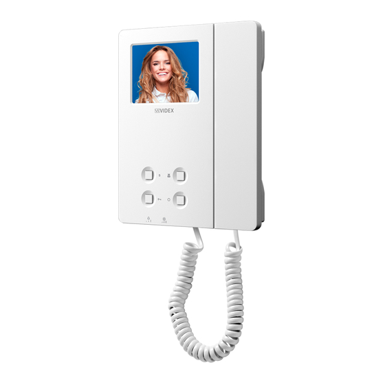
3.5" colour display videophone
27 mm
Fig. 1 Front
DESCRIPTION
An intelligent Videophone using 3.5" full colour active matrix
LCD monitor for VX2300. Including 4 buttons "service", "privacy/
bus relay activation", "door-open/intercommunicating call" and
"camera recall" plus 3 LED's for visual indication of all functions.
Adjustments & programmable options: call tone volume on 3 lev-
els (low, medium, high), picture hue, brightness and contrast, call
tone melody, number of rings, privacy duration and address. Also
includes a local bell function. The Art. 6286 is surface mount.
PUSH BUTTONS
Service push button
When pressed it links internally the terminals C and NO on the connection terminals.
Privacy ON-OFF push button
To enable the function press this button when the videophone is in stand-by. The service is automatically disabled when
the programmed time expires (the privacy duration time can be programmed) or manually by pressing again the button.
Activate bus relay board Art. 2305 push button
To activate a bus relay, during a conversation, press this button quickly as many times as the address value of the relay.
Door open push button
Press this button to open the door when you are in conversation.
Intercommunication push button
For an intercommunicating call, pick up the handset and press as many times as the extension or address value to call (see
SW3 Intercommunication Settings).
Camera recall push button
Pick up the handset and press as many times as the DEVICE N. of the door station to switch on.
Camera switch push button
If the door station uses the Art. 4303N plus the Art. 4330N, pressing this button during a conversation switches the video
signal coming from the camera module to the video signal coming from the camera module input for external camera.
During the conversation, press and keep pressed the button until the camera switches. Repeat the operation to switch back
to main camera.
Art. 6286 - Installation instructions
144 mm
B
SW
E
Fig. 2 Back
LEGEND
Connection terminals
A
Bus termination switch
B
8 Way dip switch bank
C
4 Way dip switch bank
D
Contrast adjustment trimmer
E
Hue adjustment trimmer
F
Brightness control
G
Call tone volume switch
H
- 1 -
A
PT3 PT2
PT1
SW1
G
H
66251110 - V4.1 - 31/05/19
R01A
C
D
F
Advertisement

Related Manuals for Videx 6200 Series


Summary of Contents for Videx 6200 Series
- Page 1 6200 Series Art. 6286 3.5" colour display videophone R01A 27 mm 144 mm PT3 PT2 Fig. 1 Front Fig. 2 Back DESCRIPTION LEGEND An intelligent Videophone using 3.5” full colour active matrix Connection terminals LCD monitor for VX2300. Including 4 buttons “service”, “privacy/ Bus termination switch bus relay activation”, “door-open/intercommunicating call”...
-
Page 2: Melody Selection
6200 Series Art. 6286 3.5" colour display videophone LEDS CONTROLS Call tone volume control Privacy on LED (3 levels). It illuminates when the privacy service is enabled. Brightness control Generic use LED (sliding wheel). It is controlled from the terminals +DOL and –DOL. Nor- Colour intensity control trimmer mally used to signal the door status (open or closed). - Page 3 6200 Series Art. 6286 3.5" colour display videophone VIDEOPHONE ADDRESS – SW1.1..7 The table below shows how to set the address of the videophone. Considering that ON = 1 and OFF = 0, multiply each digit for the relevant decimal weight then sum values obtained to get the address: E.g. as highlighted in...
-
Page 4: Specification
6200 Series Art. 6286 3.5" colour display videophone CONNECTION TERMINALS SIGNALS SPECIFICATION Housing/Mounting: 6200 Series Videophones / surface BUS1 Bus input mount BUS2 Bus input Push buttons: Yes, 4 Ground Programming: Yes, carried out by the buttons and +12Vdc power supply input (Art. 323/12 or the dip-switches located on the rear Art. AMR2-12) for version with Memory Board op-... - Page 5 6200 Series 6200 Series Videophone wall mounting instructions Fig. 1 Fig. 2 Fig. 3 Fig. 5 Fig. 4 Fig. 6 Fig. 7 1. In order to install the videophone, it is necessary to remove the cover, which contains all the electronics, from the base: firstly disconnect the handset from the videophone (by removing its plug from the videophone) then insert a 5.5mm flat screw driv-...
- Page 6 Serie 6200 Art. 6286 Videocitofono 3,5" a colori R01A 27 mm 144 mm PT3 PT2 Fig. 1 Fronte Fig. 2 Retro DESCRIZIONE LEGENDA Videocitofono a colori con monitor LCD TFT da 3,5” per siste- Morsettiera di connessione mi videocitofonici VX2300. Sono disponibili 4 pulsanti di cui 2 Switch di terminazione del BUS con funzioni multiple: “Servizio”, “privacy”, “apri-porta/chiamata Dip-switch ad 8 vie...
- Page 7 Serie 6200 Art. 6286 Videocitofono 3,5" a colori REGOLAZIONI Regolazione volume della nota di chiamata LED privacy on (3 livelli). Si illumina quando il servizio è attivo. Regolazione luminosità. LED ad uso generico È alimentato dai morsetti +DOL e –DOL della scheda di Trimmer di regolazione della saturazione connessione Art. 5980.
- Page 8 Serie 6200 Art. 6286 Videocitofono 3,5" a colori INDIRIZZO VIDEOCITOFONO – SW1.1..7 La tabella sottostante mostra come impostare l’indirizzo del videocitofono. Considerando che ON = 1 e OFF = 0, moltiplicare ciascuna cifra per il relativo peso decimale quindi sommare i valori ottenuti per calcolare l’indirizzo: 1 2 3 4 5 6 7 Es.
-
Page 9: Specifiche Tecniche
Serie 6200 Art. 6286 Videocitofono 3,5" a colori SEGNALI MORSETTERIA DI CONNESSIONE SPECIFICHE TECNICHE Formato/Montaggio: Videocitofoni Serie 6200 / da super- BUS1 Ingresso BUS ficie BUS2 Ingresso BUS Pulsanti: Si, 4 Massa Programmazione: Si, tramite i dip-switch accessibili dal Ingresso alimentazione +12Vdc (Art. 323/12 o retro del videocitofono e pulsanti Art. AMR2-12) per versione con Memoria Video Controlli:... - Page 10 Serie 6200 Serie 6200 Istruzioni di installazione a parete Fig. 1 Fig. 2 Fig. 3 Fig. 5 Fig. 4 Fig. 6 Fig. 7 1. Per installare il videocitofono è necessario aprirlo separando la base dal coperchio che ospita tutta l’elettronica dello stesso: scollegare la cornetta dal videocitofono rimuovendo il relativo plug quindi inserire la punta di un giravite piatto da 5.5mm nella clip dopodiché...
- Page 11 (power off then power on). 12Vac Title: Data creazione: Foglio 02/02/2017 Titolo: Data modifica: 06/02/2017 Videx Electronics S.p.A. Notes: Autore: Marco Rongoni Via del Lavoro 1, 63020 Monte Giberto (AP) Note: Cod.File: Phone: +39 0734 631669 - Fax +39 0734 631669 esvk-62h-001.dwg www.videx.it - info@videx.it...
- Page 12 - 12 - 66251110 - V4.1 - 31/05/19...
- Page 13 - 13 - 66251110 - V4.1 - 31/05/19...
- Page 14 (power off then power on). Title: Data creazione: Foglio 02/02/2017 Titolo: Data modifica: 06/02/2017 Videx Electronics S.p.A. Notes: Autore: Marco Rongoni Via del Lavoro 1, 63020 Monte Giberto (AP) Note: Cod.File: Phone: +39 0734 631669 - Fax +39 0734 631669 esvk-62h-003.dwg www.videx.it - info@videx.it...
- Page 15 DISPOSAL In accordance with the Legislative Decree no. 49 of 14 March 2014 “Implementation of the Directive 2012/19/EU on waste electrical and electronic equipment (WEEE)”. The crossed-out bin symbol on the equipment or on the packaging indicates that when the product reaches the end of its lifetime, it must be collected separately from mixed municipal waste.
- Page 16 MANUFACTURER VIDEX ELECTRONICS S.P.A. FABBRICANTE Via del Lavoro, 1 FABRICANT 63846 Monte Giberto (FM) Italy FABRICANTE Tel (+39) 0734 631669 FABRIKANT Fax (+39) 0734 632475 www.videx.it - info@videx.it CUSTOMER SUPPORT VIDEX ELECTRONICS S.P.A. UK Customers only: SUPPORTO CLIENTI www.videx.it - technical@videx.it...
Need help?
Do you have a question about the 6200 Series and is the answer not in the manual?
Questions and answers