Videx 6200 Series Manual
3.5" colour display videophone
Hide thumbs
Also See for 6200 Series:
- Manual (44 pages) ,
- User manual (29 pages) ,
- Quick manual (16 pages)
Advertisement
Available languages
Available languages
Quick Links
6200 Series
Art. 6276
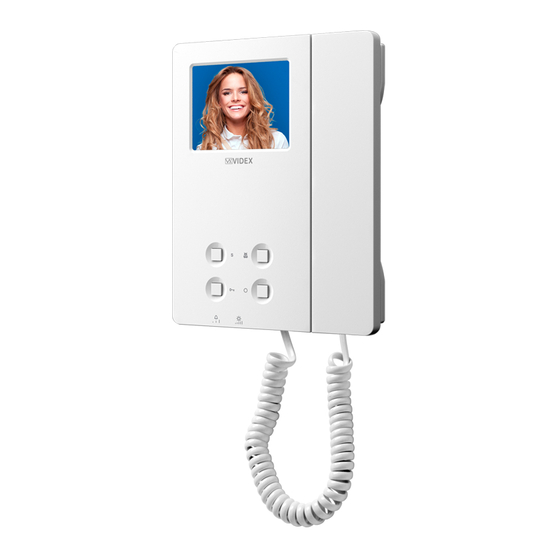
3.5" colour display videophone
27 mm
Fig. 1 Front
DESCRIPTION
Surface mount videophone for VX2200 digital systems using com-
posite video signal (coax) or balanced (twisted pair) incorporating
a 3.5" Hi-Res full colour active matrix LCD monitor, with "camera re-
call", "door open/concierge call", "service" and "privacy" button.
2 LED's one for generic use (door opening usually) and one to
indicate privacy service enabled.
Programmable settings: privacy duration, video mode (coax or
balanced), melody and number of rings.
Adjustments: call tone volume (3 levels), microphone volume,
picture hue, contrast and brightness.
PUSH BUTTONS
Service button
When pressed, shorts terminal SW to SW (Max 24 Vdc 50mA).
Privacy service
Press to enable the privacy service. The LED
when the programmed time expires.
Door Open Push Button
• During a conversation, operation of this button will release the door from where the call originated. This will be confirmed
by an acoustic tone. If terminal DOL is connected, the "door open" LED under the symbol
• When the system is in stand-by, picking up the handset and pressing the buttons will book a call to the concierge (If
available).
Camera recall
When the system is in standby (no calls on the system), pick up the handset then press this button to open the SPEECH/
VIDEO to the door station. Press as many time as the ID value of the door panel to connect to.
Art. 6276 - Installation instructions
144 mm
turns on. The service is deactivated by pressing again the same button or
D
F
Fig. 2 Back
LEGEND
A
Connection terminals
B
8 Way dip switch bank to set videophone address
C
4 Way dip switch bank to set video mode
D
Contrast adjustment trimmer
E
Hue adjustment trimmer
F
Microphone volume adjustment trimmer
G
Brightness control sliding wheel
H
Call tone volume switch
I
RJ-45 connector
- 1 -
A
E
PT1 PT2
G
PT3
H
VR1
SW2
will also illuminate.
66251125 - V2.0 - 31/05/18
I
B
C
Advertisement

Related Manuals for Videx 6200 Series


Summary of Contents for Videx 6200 Series
- Page 1 6200 Series Art. 6276 3.5" colour display videophone 27 mm 144 mm PT1 PT2 Fig. 1 Front Fig. 2 Back DESCRIPTION LEGEND Surface mount videophone for VX2200 digital systems using com- Connection terminals posite video signal (coax) or balanced (twisted pair) incorporating 8 Way dip switch bank to set videophone address a 3.5”...
- Page 2 6200 Series Art. 6276 3.5" colour display videophone LEDS CONTROLS AND ADJUSTMENTS Privacy on LED Contrast adjustment trimmer* It illuminates when the privacy service is enabled, Rotate anticlockwise to increase or clockwise to when pressing the service button or during program- decrease.
- Page 3 6200 Series Art. 6276 3.5" colour display videophone TO SET THE VIDEO MODE AND TERMINATION The videophone can operate with either composite video signal (coax cable) or balanced video signal (two wires). Switches 1 & 2 of DSW2 are used to set video mode while switches 3 & 4 are for video termination.
- Page 4 6200 Series Art. 6276 3.5" colour display videophone TECHNICAL SPECIFICATION CONNECTION TERMINALS SIGNALS Working Voltage: 17÷20Vdc 12Vdc output to supply coax video distributor Power Consumption: During a call: 200mA Art. 894N During a conversation: 120mA Video power supply 17÷20Vdc Working Temperature: -10°C +50°C Balanced video signal V1 sync.
- Page 5 6200 Series 6200 Series Videophone wall mounting instructions Fig. 1 Fig. 2 Fig. 3 Fig. 5 Fig. 4 Fig. 6 Fig. 7 1. In order to install the videophone, it is necessary to remove the cover, which contains all the electronics, from the base: firstly disconnect the handset from the videophone (by removing its plug from the videophone) then insert a 5.5mm flat screw driv-...
- Page 6 Serie 6200 Art. 6276 Videocitofono 3,5" a colori 27 mm 144 mm PT1 PT2 Fig. 1 Fronte Fig. 2 Retro DESCRIZIONE LEGENDA Videocitofono per sistemi digitali VX2200 con segnale video com- Morsettiera di connessione posito (coassiale) o bilanciato (2 fili) con monitor a colori LCD TFT Dip-switch ad 8 vie per l’indirizzo del videocifotono da 3,5”, pulsante “auto-accensione”, pulsante “apri-porta/chiama- Dip-switch a 4 vie per il settaggio del modo video...
- Page 7 Serie 6200 Art. 6276 Videocitofono 3,5" a colori CONTROLLI E REGOLAZIONI Trimmer regolazione contrasto* LED privacy on Ruotare in senso antiorario per incrementare o Si illumina quando il servizio è attivo, quando si preme orario per diminuire. il pulsante di servizio o in modalità programmazione. *Non disponibile su alcune versioni di LCD.
- Page 8 Serie 6200 Art. 6276 Videocitofono 3,5" a colori PER IMPOSTARE IL MODO VIDEO E LA TERMINAZIONE Il videocitofono può funzionare con il segnale video composito (cavo coassiale) o con il segnale video bilanciato (2 fili). Gli switch 1 e 2 di DSW2 permettono di impostare il modo video mentre tramite gli switch 3 e 4 è possibile abilitare la terminazione video. MODO VIDEO - DSW2 TERMINAZIONE VIDEO 75 OHM Switch 1,2...
- Page 9 Serie 6200 Art. 6276 Videocitofono 3,5" a colori SPECIFICHE TECNICHE SEGNALI MORSETTIERA DI CONNESSIONE Tensioni d’alimentazione: 17÷20Vdc Uscita 12Vdc per alimentazione distributore video Assorbimenti: Durante la chiamata: 200mA Art. 894N Durante la conversazione: 120mA Ingresso alimentazione video 17÷20Vdc Temperatura di Lavoro: -10°C +50°C Sincronia V1 segnale video bilanciato (modo segnale video bilanciato.) MEMORIA VIDEO...
- Page 10 Serie 6200 Serie 6200 Istruzioni di installazione a parete Fig. 1 Fig. 2 Fig. 3 Fig. 5 Fig. 4 Fig. 6 Fig. 7 1. Per installare il videocitofono è necessario aprirlo separando la base dal coperchio che ospita tutta l’elettronica dello stesso: scollegare la cornetta dal videocitofono rimuovendo il relativo plug quindi inserire la punta di un giravite piatto da 5.5mm nella clip dopodiché...
- Page 11 66251125 - V2.0 - 31/05/18...
- Page 12 316x others Title: Data creazione: Foglio 16/09/2016 Titolo: Data modifica: 20/10/2016 Videx Electronics S.p.A. Notes: Autore: Marco@videx.it Via del Lavoro, 1 - 63846 Monte Giberto (FM) Note: Cod.File: Phone: +39 0734 631669 - Fax +39 0734 631669 224KVD139A.dwg www.videx.it - info@videx.it...
- Page 13 L - + - V1 V2 Close L - + - V1 V2 Art.6276 Art.6276 Address N. 11 Address N. 12 Art.6378 Art.6378 Address N. 9 Address N. 10 L - + - V1 V2 L - + - V1 V2 Art.6276 Art.6276 Address N.
- Page 14 - 14 - 66251125 - V2.0 - 31/05/18...
- Page 15 - 15 - 66251125 - V2.0 - 31/05/18...
- Page 16 MANUFACTURER VIDEX ELECTRONICS S.P.A. FABBRICANTE Via del Lavoro, 1 FABRICANT 63846 Monte Giberto (FM) Italy FABRICANTE Tel (+39) 0734 631669 FABRIKANT Fax (+39) 0734 632475 www.videx.it - info@videx.it CUSTOMER SUPPORT VIDEX ELECTRONICS S.P.A. UK Customers only: SUPPORTO CLIENTI VIDEX SECURITY LTD www.videx.it - technical@videx.it...
Need help?
Do you have a question about the 6200 Series and is the answer not in the manual?
Questions and answers