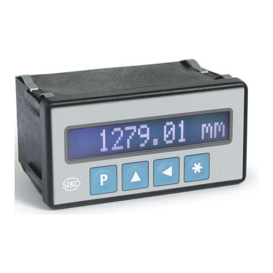
Summary of Contents for Siko MA502
- Page 1 MA502 Magnetbandanzeige Deutsch Originalmontageanleitung Seite 2 Magnetic Display English Translation of the Original Installation Instructions page 12 329/15...
-
Page 2: Table Of Contents
4.1 Mechanische Montage 4.2 Elektrische Installation 4.3 Option serielle Schnittstelle RS232 oder RS485 4.4 Option Schaltausgänge 5 Inbetriebnahme 6 Transport, Lagerung, Wartung und Entsorgung 7 Zubehör Tischgehäuse 8 Technische Daten MA502 · Datum 28.08.2015 · Art. Nr. 81774 · Änd. Stand 329/15... -
Page 3: Dokumentation
Todesfolge, Sachschäden oder ungeplanten Gerätereaktionen führen können, sofern Sie die gegebenen Anweisungen missachten. Gefährdungen, die zu schweren Körperverletzungen, Sachschäden oder WARNUNG ungeplanten Gerätereaktionen führen können, sofern Sie die gegebenen Anweisungen missachten. MA502 · Datum 28.08.2015 · Art. Nr. 81774 · Änd. Stand 329/15... -
Page 4: Zielgruppe
Geräte/Systeme gemäß den Standards der Sicherheitstech- nik in Betrieb zu nehmen, zu erden und zu kennzeichnen. 2.4 Grundlegende Sicherheitshinweise Explosionsgefahr GEFAHR ` Magnetbandanzeige nicht in explosionsgefährdeten Zonen einsetzen. MA502 · Datum 28.08.2015 · Art. Nr. 81774 · Änd. Stand 329/15... -
Page 5: Identifikation
Gehäuse lose halten. 2. Die seitliche Zentrierung leicht andrücken und das Gehäuse in den Ausschnitt schieben bis die Panel-Clips vollständig einrasten. Schalttafelausschnitt Panel-Clip Zentrierung Abb. 1: Einbau MA502 · Datum 28.08.2015 · Art. Nr. 81774 · Änd. Stand 329/15... -
Page 6: Elektrische Installation
• 9 pol. Steckleiste (siehe Abb. 2: Anschluss Sensor (Eingang 1-Kanal) Litzenquerschnitt ≤2.5 mm² PE Anschluss für Flachsteckhülse Sensor 1 (Eingang 2-Kanal) Sensor 2 (Eingang 2-Kanal) MA502 · Datum 28.08.2015 · Art. Nr. 81774 · Änd. Stand 329/15... -
Page 7: Option Serielle Schnittstelle Rs232 Oder Rs485
Klemmen 3 (GND), 6 (TXD/ DÜA) und 5 (RXD/ DÜB). Belegung Klemmleiste Abb. 4: Anschlussschema Schnittstellenoption RS232 MA502 · Datum 28.08.2015 · Art. Nr. 81774 · Änd. Stand 329/15... -
Page 8: Option Schaltausgänge
5 Inbetriebnahme Tastenfunktionen, Programmiermodus, Parameterbeschreibung, Eingabe- ACHTUNG modus etc. siehe Beiblatt Softwarebeschreibung. Nach ordnungsgemäßem Anschluss und dem Einschalten der Betriebs- spannung erfolgt: • Hardwarekennung (z. B. "SIKO:MA502") ca. 1.5 s MA502 · Datum 28.08.2015 · Art. Nr. 81774 · Änd. Stand 329/15... -
Page 9: Transport, Lagerung, Wartung Und Entsorgung
Stoffe und sind zugleich Wertstoffträger. Die Mangetbandan- zeige muss deshalb nach seiner endgültigen Stilllegung einem Recycling zugeführt werden. Die Umweltrichtlinien des jeweiligen Landes müssen hierzu beachtet werden. MA502 · Datum 28.08.2015 · Art. Nr. 81774 · Änd. Stand 329/15... -
Page 10: Zubehör Tischgehäuse
20 mA bei 115 V AC 10 mA bei 230 V AC Anzeige/Anzeigenbereich 12-stellig, LCD Punktmatrix, -9999999 ... 9999999, Vorzei- hinterleuchtet chen, Einheiten Schaltausgänge mit oder ohne 2x 30 V ≤100 mA Schnittstelle ohne, RS232, RS485 MA502 · Datum 28.08.2015 · Art. Nr. 81774 · Änd. Stand 329/15... - Page 11 Luftfeuchtigkeit ≤95 % Betauung nicht zulässig EN 61000-6-2 Störfestigkeit / Immission EN 61000-6-4 Störaussendung / Emission Schutzart IP40 Gesamtgerät EN 60529 IP60 frontseitig bei Schaltta- EN 60529 feleinbau MA502 · Datum 28.08.2015 · Art. Nr. 81774 · Änd. Stand 329/15...
- Page 12 4.2 Electrical Installation 4.3 Optional serial RS232 or RS485 interface 4.4 Switching output option 5 Commissioning 6 Transport, Storage, Maintenance and Disposal 7 Accessory benchtop housing 8 Technical data MA502 · Date 28.08.2015 · Art. No. 81774 · Mod. status 329/15...
-
Page 13: Documentation
Danger that may cause minor injury, property damage or unplanned device CAUTION reactions if you disregard the instructions given. MA502 · Date 28.08.2015 · Art. No. 81774 · Mod. status 329/15... -
Page 14: Target Group
Please check the particular type of unit and type number from the identifi- cation plate. Type number and the corresponding version are indicated in the delivery documentation. e. g. MA502 0023 version number type of unit MA502 · Date 28.08.2015 · Art. No. 81774 · Mod. status 329/15... -
Page 15: Installation
` Use strands with suitable ferrules. ` Prior to switching on check all mains and plug connections. ` Switch on operating voltage together with downstream electronics (e. g., control unit). MA502 · Date 28.08.2015 · Art. No. 81774 · Mod. status 329/15... - Page 16 PE tag for connection Sensor 1 (input 2-channel) Sensor 2 (input 2-channel) RS232 RS485 switching output Fig. 3: Connection diagram MA502 · Date 28.08.2015 · Art. No. 81774 · Mod. status 329/15...
-
Page 17: Optional Serial Rs232 Or Rs485 Interface
Fig. 4: Connection diagram RS232 interface option Designation terminal Fig. 5: Connection diagram RS485 interface option MA502 · Date 28.08.2015 · Art. No. 81774 · Mod. status 329/15... -
Page 18: Switching Output Option
There are two operating modes accessible via the keyboard: 1. Programming mode: to program the display at initial installation. 2. Input mode: to enter parameters/select functions used during stan- dard operation. MA502 · Date 28.08.2015 · Art. No. 81774 · Mod. status 329/15... -
Page 19: Transport, Storage, Maintenance And Disposal
Observe the environment protec- tion guidelines of your country. 7 Accessory benchtop housing (not included in the scope of delivery) • Accessory SIKO art. no. "TG01" Fig. 7: Benchtop housing MA502 · Date 28.08.2015 · Art. No. 81774 · Mod. status 329/15... -
Page 20: Technical Data
Ambient temperature 0 ... 50 °C Storage temperature -20 ... 80 °C Relative humidity ≤95 % condensation inadmissible EN 61000-6-2 interference resistance / immis- sion EN 61000-6-4 emitted interference / emission MA502 · Date 28.08.2015 · Art. No. 81774 · Mod. status 329/15... - Page 21 MA502 Technical data English Ambient conditions Additional information Protection category IP40 whole device EN 60529 IP60 at the front with switch- EN 60529 board installation MA502 · Date 28.08.2015 · Art. No. 81774 · Mod. status 329/15...
- Page 22 MA502...
- Page 23 MA502...
- Page 24 SIKO GmbH Weihermattenweg 2 79256 Buchenbach Telefon/Phone + 49 7661 394-0 Telefax/Fax + 49 7661 394-388 E-Mail info@siko.de Internet www.siko-global.com Service support@siko.de...


Need help?
Do you have a question about the MA502 and is the answer not in the manual?
Questions and answers