Carel pCO1 Instructions Manual
Modular standard hp chiller 1/4 compressors for carel driver
Hide thumbs
Also See for pCO1:
- User manual (56 pages) ,
- Application program (48 pages) ,
- Manual (40 pages)

Subscribe to Our Youtube Channel
Related Manuals for Carel pCO1


Summary of Contents for Carel pCO1
- Page 1 Program for pCO¹ pCO pCOC 2 and Modular Standard HP Chiller 1/4 compressors for Carel driver Manual version 1.0 – 07 July 2003 FLSTDmMC0E Program code:...
- Page 3 Do we want you to save you time and money? We can assure you that reading this manual to the full will ensure correct installation and safe use of the product described here. IMPORTANT WARNINGS BEFORE INSTALLING OR CARRYING OUT ANY JOBS ON THE APPLIANCE, CAREFULLY READ AND FOLLOW THE INSTRUCTIONS IN THIS MANUAL.
-
Page 5: Table Of Contents
INDEX APPLICATIONS AND FUNCTIONS PERFORMED BY THE SOFTWARE ..................3 THE USER TERMINAL ....................................4 PLAN MANAGEMENT AMONG SCREENS ............................6 HOW TO ASSIGN THE PLAN ADDRESSES ............................6 INSTALLING DEFAULT VALUES................................7 SELECTING THE LANGUAGE ................................. 7 LIST OF INPUTS/OUTPUTS..................................8 CHILLER-ONLY UNIT - MACHINE TYPE “0”... -
Page 7: Applications And Functions Performed By The Software
Built-in terminal management (on pCO² only) Management of ratiometric probes for pressure control (on pCO only) EVD driver for piloting the EXV valve. Multilingual management. Accessories Supervision with serial card RS485 (CARE1 or MODBUS protocol) Carel code +030221236- Rel. 1.0 dated 7 July 2003... -
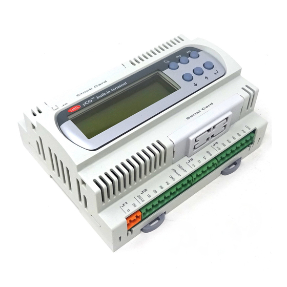
Page 8: The User Terminal
OFF, it enables winter operation in machine configurations 4 and 5. BLUE with the unit OFF, it enables summer operation in machine configurations 4 and 5. Carel code +030221236- Rel. 1.0 dated 7 July 2003... - Page 9 MASK LOOP: as there are no keys which directly put in the screen loop, press the Prog key to show the loop list. Then use the arrow keys to locate in line with the selected loop and then press Enter to access it. Carel code +030221236- Rel. 1.0 dated 7 July 2003...
-
Page 10: Plan Management Among Screens
ADDRESSING PCO2, EXTERNAL TERMINALS AND VALVE DRIVERS The following are the addresses to be set on the pCO2 cards, external terminals and valve drivers. If you are using the pCO1 cards, consult the previous paragraph for the cards only, whereas the following information does apply to the terminals and drivers. -
Page 11: Installing Default Values
When you have checked the connections between the cards and terminals, power up the pCO card/s*.When the machine is powered up, the software automatically installs the default values selected by CAREL for all the chiller and driver configuration parameters. This section tells you how to reset default values to return to the initial conditions. Therefore, this operation need not be carried out at the first power-up. -
Page 12: List Of Inputs/Outputs
Circuit 3 fan Circuit 1 fan Circuit 3 fan Circuit 1 fan Circuit 3 fan Circuit 2 fan Circuit 4 fan Circuit 2 fan Circuit 4 fan Circuit 2 fan Circuit 4 fan Carel code +030221236- Rel. 1.0 dated 7 July 2003... -
Page 13: Chiller-Only Unit With Freecooling - Machine Type "1
Circuit 1 fan Circuit 3 fan Circuit 1 fan Circuit 3 fan Circuit 1 fan Circuit 3 fan Freecooling On/Off Circuit 4 fan Freecooling On/Off Circuit 4 fan Freecooling On/Off Circuit 4 fan Carel code +030221236- Rel. 1.0 dated 7 July 2003... -
Page 14: Chiller-Only Unit - Machine Type "2
Slave Circuit 1 fan speed Circuit 2 fan speed Circuit 1 fan speed Circuit 2 fan speed Circuit 1 fan speed Circuit 2 fan speed control control control control control control Carel code +030221236- Rel. 1.0 dated 7 July 2003... -
Page 15: Chiller-Only Unit With Freecooling - Machine Type "3
Circuit 1 fan speed Circuit 2 fan speed Circuit 1 fan speed Circuit 2 fan speed control control control control control control Freecooling Freecooling modulating Freecooling modulating valve valve modulating valve Carel code +030221236- Rel. 1.0 dated 7 July 2003... -
Page 16: Chiller Unit With Heat Pump - Machine Type "4
Slave Circuit 1 fan speed Circuit 2 fan speed Circuit 1 fan speed Circuit 2 fan speed Circuit 1 fan speed Circuit 2 fan speed control control control control control control Carel code +030221236- Rel. 1.0 dated 7 July 2003... -
Page 17: Chiller Unit With Heat Pump And Total Recovery - Machine Type "5
Slave Circuit 1 fan speed Circuit 2 fan speed Circuit 1 fan speed Circuit 2 fan speed Circuit 1 fan speed Circuit 2 fan speed control control control control control control Carel code +030221236- Rel. 1.0 dated 7 July 2003... -
Page 18: List Of Parameters
0 to 99 Summer set-point 12.0 see P1 °C Winter set-point 45.0 see P2 °C Recovery priority Evap. Evap.Recov. Recovery set-point 45,0 -99.9 to 99.9 °C Recovery differential 0.0 to 99.9 °C Carel code +030221236- Rel. 1.0 dated 7 July 2003... - Page 19 Enable clock card Enable pump - down Minimum pump - down time 0 to 999 seconds Delay between capacity controls 0 to 99 seconds Capacity controls logic N.C. N.C / N.A. Carel code +030221236- Rel. 1.0 dated 7 July 2003...
- Page 20 Driver 2 dead band during chiller operation 0 to 9.9 °C Driver 2 superheat set-point during heat pump 2.0 to 50.0 °C operation Driver 2 dead band during heat pump operation 0 to 9.9 °C Carel code +030221236- Rel. 1.0 dated 7 July 2003...
- Page 21 0 to 500 seconds operation Threshold for MOP protection during chiller 40,0 -50.0 to 99.9 °C operation Integral time of threshold for MOP protection during 0 to 25.5 seconds chiller operation Carel code +030221236- Rel. 1.0 dated 7 July 2003...
- Page 22 Delay high temperature intake alarm 0 to 3600 seconds Delay LOP alarm 0 to 3600 seconds Delay MOP alarm 0 to 3600 seconds Input new constructor-driver password 1234 0 to 9999 Carel code +030221236- Rel. 1.0 dated 7 July 2003...
-
Page 23: Screens
PSW P0 PSW Z0 → " CONFIGURATION " " " PSW A4 " " " " " " " " " " ····· " " PSW FOR EEV DRIVER → ····· Carel code +030221236- Rel. 1.0 dated 7 July 2003... -
Page 24: Control
Minimum limit of temperature at outlet (powers down all compressors without observing the disabling time) • Maximum limit of temperature at outlet (powers down all compressors without observing the disabling time) Carel code +030221236- Rel. 1.0 dated 7 July 2003... - Page 25 If the temperature falls below the minimum limit, the compressors are forcibly powered down if the times were not satisfied (this control is introduced to prevent the unit entering antifreeze alarm status). Carel code +030221236- Rel. 1.0 dated 7 July 2003...
-
Page 26: Electronic Expansion Valve
Alco EX8 Sporlan SEI 0.5 - 11 Sporlan SEi 25 Sporlan SEI 50 – SHE 250 Danfoss ETS 50 Danfoss ETS 100 Carel E2V**P Carel E2V**A Custom (other type of valve) Carel code +030221236- Rel. 1.0 dated 7 July 2003... -
Page 27: Driver Parameters
10.1.10 Configuration of the evaporation pressure probe (FE) This screen is used for setting the minimum and maximum values of the refrigerant pressure probe range at the outlet of the evaporator connected to the driver. Carel code +030221236- Rel. 1.0 dated 7 July 2003... -
Page 28: Special Function "Ignore
Rotation occurs only among the compressors and not among the capacity controls. 11.1 ROTATION-FREE MANAGEMENT • Power-up sequence: C1,C2,C3,C4 • Power-down sequence: C4,C3,C2,C1 11.2 MANAGEMENT WITH FIFO ROTATION (FIRST IN FIRST OUT) • Power-up sequence: C1,C2,C3,C4 • Power-down sequence: C1,C2,C3,C4 Carel code +030221236- Rel. 1.0 dated 7 July 2003... -
Page 29: Condensation Control
With the compressor ON, when this threshold is reached, the compressor is capacity-control forced until pressure drops below the set-point - differential (both can be set). With the compressor OFF when this threshold is reached, compressor forcing is replaced by forced power up of the fans. Carel code +030221236- Rel. 1.0 dated 7 July 2003... -
Page 30: Defrosting Control For Water/Air Machine
When it has finished, the next circuit needing to defrost enters defrosting and the others continue to wait. Defrosting a circuit with time/temperature control temperature set.stop set.start time Defrosting cycle Carel code +030221236- Rel. 1.0 dated 7 July 2003... - Page 31 The fans are usually OFF during the defrosting cycle. They are activated only if the pressure probes were enabled and pressure exceeds the prevent threshold - in this way the unit is prevented from going into high pressure alarm status. Carel code +030221236- Rel. 1.0 dated 7 July 2003...
-
Page 32: Controlling Unit Recovery
A (recovery) Valve B (use) Valve C (summer/winter) Chiller only Chiller + recovery Recovery only Winter operation valve A (recovery) Valve B (use) Valve C (summer/winter) Heat pump Recovery only Defrosting Carel code +030221236- Rel. 1.0 dated 7 July 2003... -
Page 33: Free Cooling Control
Free Cooling battery and the set Free Cooling delta. External T. < Free Cooling Input T. – Free Cooling Delta If this condition occurs, the control manages Free Cooling, enabling /disabling the dedicated devices. Carel code +030221236- Rel. 1.0 dated 7 July 2003... -
Page 34: Free Cooling Thermostat
The Free Cooling valve will, in any event, be maintained fully open to provide as high as possible a thermal yield even at minimum ventilating capacity. Carel code +030221236- Rel. 1.0 dated 7 July 2003... -
Page 35: Free Cooling Disabling Conditions
Control Set-point - Free Cooling Differential +5.0% Free Cooling Differential The step amplitude is fixed at 5.0% of the set Free Cooling control differential. Carel code +030221236- Rel. 1.0 dated 7 July 2003... -
Page 36: Free Cooling On/Off Valve With Stepped Condensation
(Number of Master fans X number of cards) It is assumed that all the circuits controlled by the pCO cards making up the system are equivalent and that the number of controlled devices is the same. Carel code +030221236- Rel. 1.0 dated 7 July 2003... -
Page 37: Free Cooling On/Off Valve With Inverter Controlled Condensation
If necessary, Value 0-10 Volt can be further limited downward according to the minimum output voltage value set on the screen. All proportional outputs relating to the different units of the system will be piloted in parallel Carel code +030221236- Rel. 1.0 dated 7 July 2003... -
Page 38: Volt Free Cooling On/Off Valve
(Number of Master fans X number of cards) It is assumed that all the circuits controlled by the pCO cards making up the system are equivalent and that the number of controlled devices is the same. Carel code +030221236- Rel. 1.0 dated 7 July 2003... -
Page 39: Volt Free Cooling Valve With Inverter Controlled Condensation
For the Free Cooling valve, the setting field ranges from 25 to 100% of the differential. For the condensation inverter, the setting field ranges from 0 to 75% of the differential. Carel code +030221236- Rel. 1.0 dated 7 July 2003... - Page 40 The devices, whether they are valve or fans, will be activated in the second half of the control differential through the effect of the integrating control. Their activation will be tied to the set integrating constant: the slower it is, the greater the value attributed to the specific parameter. Carel code +030221236- Rel. 1.0 dated 7 July 2003...
-
Page 41: Antifreeze Control
Antifreeze control is always enabled, even if the machine is OFF, both in summer and winter operating modes. Note: the antifreeze alarm on any pCO unit shuts down the entire machine. Carel code +030221236- Rel. 1.0 dated 7 July 2003... -
Page 42: Alarms
The pCO* boards’ considerable buffer space means events can be saved in the STANDARD log, which is always available on the various boards. If there is no clock card (optional extra on pCO1 and pCOC, built-in feature on pCO2), the STANDARD log just gives the alarm code. - Page 43 Wizard. WinLOAD does not need application software files as it can procure all the information required directly from the pCO1 – pCO2 board’s resident application software.
-
Page 44: Alarm Table
Driver2 - Valve not shut at power-down *Circuit man. AL73 Driver2 - Intake high temperature Settable AL75 Time-out for non-shut valve, EEPROM or *Circuit battery not charging driver 2 AL77 Driver 2 offline *Circuit man. 30 sec. Carel code +030221236- Rel. 1.0 dated 7 July 2003... -
Page 45: Short Summary Of Alarms Coming From Driver
(valve not fully closed after last blackout) • high intake temperature alarm (operating temperature has exceeded max. threshold) standby due to EEPROM error/battery recharge or open valve Carel code +030221236- Rel. 1.0 dated 7 July 2003... -
Page 46: Supervisor
SUPERVISOR pCO1, pCO2 and pCOC can be connected to a local supervision PC, and to the most common BMSs (Modbus and Bacnet) To use the listed functions, you must insert the optional RS485 card or Gateway card (instruments interpreting the different communication protocols). - Page 47 DRIVER 1 alarm - EEPROM malfunctioning DRIVER 1 alarm - Battery failed or disconnected DRIVER 1 alarm - high pressure DRIVER 1 alarm - low pressure DRIVER 1 alarm - low super-heat Carel code +030221236- Rel. 1.0 dated 7 July 2003...
-
Page 48: Analogue Variables
Superheat probe temperature reading, driver 2 Evaporation pressure probe reading, driver 2 Value of driver 2 condensation temperature (if the condensation pressure probe is configured) Set-point of super-heat driver 1 Set-point of super-heat driver 2 Carel code +030221236- Rel. 1.0 dated 7 July 2003... -
Page 49: Entire Variables
Number of capacity controls per unit (equal for all units) IN/OUT Number of condensation fans (1-3 for single condenser, 1-2 for double condenser) Circuit 1 inverter speed Circuit 2 inverter speed Carel code +030221236- Rel. 1.0 dated 7 July 2003... - Page 50 Type of fault at driver 2 start-up Type of refrigerant Type of driver 1 electronic valve Type of driver 2 electronic valve FLOW TYPE Supervisor Digital Supervisor Entire IN/OUT Supervisor Analogue % Carel code +030221236- Rel. 1.0 dated 7 July 2003...
- Page 52 Agency: CAREL S.p.A. Via dell’Industria, 11 - 35020 Brugine - Padova (Italy) Tel. (+39) 049.9716611 Fax (+39) 049.9716600 http://www.carel.com - e-mail: carel@carel.com...
Need help?
Do you have a question about the pCO1 and is the answer not in the manual?
Questions and answers