
Related Manuals for Avalue Technology EMX-QM67


Summary of Contents for Avalue Technology EMX-QM67
- Page 1 EMX-QM67 Intel® QM67 with Core™ i7/ i5/ i3/ Celeron Mini-ITX Motherboard User’s Manual 1st Ed – 2 June 2011 Part No. E2047MQ6700R...
- Page 2 Disclaimer Avalue Technology Inc. reserves the right to make changes, without notice, to any product, including circuits and/or software described or contained in this manual in order to improve design and/or performance. Avalue Technology assumes no responsibility or liability for the use of the described product(s), conveys no license or title under any patent, copyright, or 2 EMX-QM67 User’s Manual...
- Page 3 Applications that are described in this manual are for illustration purposes only. Avalue Technology Inc. makes no representation or warranty that such application will be suitable for the specified use without further testing or modification.
- Page 4 Avalue Technology Inc. Room 805, Building 9,No.99 Tianzhou Rd., 2F keduka-Bldg, 2-27-3 Taito, Caohejing Development Area, Taito-Ku, Tokyo 110-0016 Japan Xuhui District, Shanghai Tel: +81-3-5807-2321 Tel: +86-21-5169-3609 Fax:+86-21-5445-3266 Fax: +81-3-5807-2322 Information: sales.china@avalue.com.cn Information: sales.japan@avalue.com.tw Service: service@avalue.com.tw Service: service@avalue.com.tw 4 EMX-QM67 User’s Manual...
- Page 5 (such as your sales receipt) in a shippable container. A product returned without proof of the purchase date is not eligible for warranty service. 5. Write the RMA number visibly on the outside of the package and ship it prepaid to your dealer. EMX-QM67 User’s Manual 5...
-
Page 6: Table Of Contents
PCI Express x16 slot ........................33 2.6.4 MINI PCI Express ..........................33 2.6.5 CFast Card ............................34 Jumper settings and Connectors ................35 2.7.1 Clear CMOS (CMOS1) ........................35 2.7.2 COM3, COM4, COM5 RI/+5V/+12V Select (JCOMPWR3 JCOMPWR4 JCOMPWR5) ....36 6 EMX-QM67 User’s Manual... - Page 7 Intel Anti-Theft Technology Configuration ..................64 3.6.11 AMT Configuration ......................... 65 3.6.12 USB Configuration ......................... 67 3.6.13 Super IO Configuration ........................69 3.6.13.1 Serial Port 0 configuration ........................70 3.6.13.2 Serial Port 1 configuration ........................71 EMX-QM67 User’s Manual 7...
- Page 8 PCH-IO Configuration ........................93 3.6.21 USB Configuration ......................... 95 3.6.22 PCI Express Configuration ......................96 3.6.22.1 PCI Express Root Port 1 ......................... 97 3.6.23 Boot .............................. 98 3.6.24 Security ............................100 3.6.25 Save & Exit ..........................101 8 EMX-QM67 User’s Manual...
-
Page 9: Getting Started
1.2 Packing List Before you begin installing your single board, please make sure that the following materials have been shipped: 1 x EMX-QM67 Mini-ITX Main board 1 x CD-ROM contains OS drivers ... -
Page 10: Document Amendment History
EMX-QM67 User’s Manual 1.3 Document Amendment History Revision Date Comment June 2011 Initial Release 10 EMX-QM67 User’s Manual... -
Page 11: Manual Objectives
We strongly recommend that you study this manual carefully before attempting to interface with EMX-QM67 series or change the standard configurations. Whilst all the necessary information is available in this manual we would recommend that unless you are confident, you contact your supplier for guidance. -
Page 12: System Specifications
Yes, through internal LVDS Backlight Connector LVDS Backlight Audio Realtek ALC892, 5.1 Channel HD Audio Audio Codec Line-in, Line-out, Mic-in, Front Audio Header Audio Interface Infineon SLB9635 supports TPM 1.2 Ethernet Intel 82579LM LAN1 Intel 82583V LAN2 12 EMX-QM67 User’s Manual... - Page 13 Operating Temperature 0% to 90% relative humidity, non-condensing Operating Humidity 6.69" x 6.69" (170 x 170mm) Size (L x W) Intel 82583V LAN2 1.03 lbs (0.47 Kg) Weight * Specifications are subject to change without notice. EMX-QM67 User’s Manual 13...
-
Page 14: Architecture Overview - Block Diagram
EMX-QM67 User’s Manual 1.6 Architecture Overview – Block Diagram The following block diagram shows the architecture and main components of EMX-QM67. 14 EMX-QM67 User’s Manual... -
Page 15: Hardware Configuration
EMX-QM67 User’s Manual 2. Hardware Configuration EMX-QM67 User’s Manual 15... -
Page 16: Product Overview
• DirectX® 10.1 & Open GL 3.0 let you enjoy awesome graphics performance, stunning 3D visual effect and dynamic interactivity • Memory support, integrated low voltage DDR3 memory controller • Operating system support: - Microsoft - WindRiver - Redhat - Novell - Green Hills - QNX - LinuxWorks 16 EMX-QM67 User’s Manual... - Page 17 - Mini PCI Express® x 1Gen 2 5GT/s - CFast connector SATA II interface - Five SATA ports (2 port of Gen 2.0 and 3 ports of Gen 3.0) support RAID 0,1, 5, 10 - Gigabit Ethernet Media Access Controller (GbE MAC) EMX-QM67 User’s Manual 17...
-
Page 18: Motherboard Overview
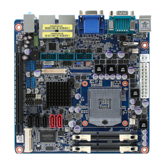
When installing the motherboard, make sure that you place it into the chassis in the correct orientation. The edge with external ports goes to the rear part of the chassis as indicated in the image below. 18 EMX-QM67 User’s Manual... -
Page 19: Screw Holes
Place four (4) screws into the holes indicated by circles to secure the motherboard to the chassis. Place this side towards the rear of the chassis. Do not over tighten the screws! Doing so can damage the motherboard. EMX-QM67 User’s Manual 19... -
Page 20: Motherboard Layout
EMX-QM67 User’s Manual 2.2.3 Motherboard Layout 20 EMX-QM67 User’s Manual... -
Page 21: Jumper And Connector List
HDMI 1.3 19-pin LAN1USB12 RJ-45 Ethernet Connector x 1 USB 2.0 Connector x 2 LAN2USB34 RJ-45 Ethernet Connector x 1 USB 2.0 Connector x 2 Audio1 Audio Line-In , Line-Out , Mic.-In 5.1 Channel Audio I/O (3 jacks) EMX-QM67 User’s Manual 21... -
Page 22: Internal Connectors
1 x 5 connector SPI Connector 4 x 2 header, pitch 2.54mm SATA1 ~ 5 SATA Data Connector * 5 7P Male connector USB56 USB78 USB Connector * 8 5 x 2 header, pitch 2.54mm USB910 USB1112 22 EMX-QM67 User’s Manual... -
Page 23: Central Processing Unit (Cpu)
If you purchased a separate CPU heatsink and fan assembly, make sure that you have properly applied Thermal Interface Material to the CPU heatsink or CPU before you install the heatsink and fan assembly. EMX-QM67 User’s Manual 23... -
Page 24: Installing The Cpu
2.4.1.1 Locate the CPU socket on the motherboard. Before installing the CPU, make sure that the socket box is facing towards you and the load lever is on your left. 2.4.1.2` Separate CPU cooler and its base first by screw drawer 24 EMX-QM67 User’s Manual... - Page 25 EMX-QM67 User’s Manual 1. Assemble the CPU FAN retention module 2. Position the CPU over the socket, making sure that the gold triangle is the same side as CPU Socket triangle. CPU Socket triangle Gold triangle EMX-QM67 User’s Manual 25...
- Page 26 3. turn the CPU lock clockwise to lock CPU The CPU fits in only one correct orientation. DO NOT force the CPU into the socket to prevent bending the connectors on the socket and damaging the CPU! 26 EMX-QM67 User’s Manual...
-
Page 27: Installing The Cpu Heatsink And Fan
Screw tightly the four fasteners. Connect the CPU fan cable to the connector on the motherboard labeled CPU_FAN. Do not forget to connect the CPU fan connector! Hardware monitoring errors can occur if you fail to plug this connector. EMX-QM67 User’s Manual 27... -
Page 28: System Memory
204-pin DDR2 DIMM. DDR3 DIMMs are notched differently to prevent installation on a DDR2 DIMM socket. The following figure illustrates the location of the sockets: 204-pin DDR3 DIMM sockets Channel Socket Channel A DIMMA1 Channel B DIMMB1 28 EMX-QM67 User’s Manual... -
Page 29: Memory Configurations
Due to CPU limitation, DIMM modules with 128 Mb memory chips or double-sided x16 memory chips are not supported in this motherboard. 2.5.3 Installing a SO-DIMM Unlock a DIMM socket by pressing the retaining clips outward. EMX-QM67 User’s Manual 29... - Page 30 Align a SO-DIMM on the socket such that the notch on the SO-DIMM matches the break on the socket. DDR3 SO-DIMM notch Unlocked retaining clip Firmly insert the SO-DIMM into the socket until the retaining clips snap back in place and the SO-DIMM is properly seated. Locked retaining clip 30 EMX-QM67 User’s Manual...
-
Page 31: Removing A So-Dimm
1. Simultaneously press the retaining clips downward to unlock the DIMM. 2. Remove the DIMM from the socket. Unlocked retaining clip Support the SO-DIMM lightly with your fingers when pressing the retaining clips. The SO-DIMM might get damaged when it flips out with extra force. EMX-QM67 User’s Manual 31... -
Page 32: Expansion Card
1. Turn on the system and change the necessary BIOS settings, if any. See Chapter 2 for information on BIOS setup. 2. Assign an IRQ to the card if needed. Refer to the tables on the next page. 3. Install the software drivers for the expansion card. 32 EMX-QM67 User’s Manual... -
Page 33: Pci Express X16 Slot
This motherboard supports one PCI Express x16. The following figure shows a graphics card installed on the PCI Express x16 slot. 2.6.4 MINI PCI Express This motherboard supports one MINI PCI Express. The following figure shows a Decode card installed on the MINI PCI Express slot. EMX-QM67 User’s Manual 33... -
Page 34: Cfast Card
EMX-QM67 User’s Manual 2.6.5 CFast Card This motherboard supports one CFast Card connector and its location is on button side of MB. The following figure shows a CFast Card installed on the CFast Card connector.. 34 EMX-QM67 User’s Manual... -
Page 35: Jumper Settings And Connectors
You do not need to clear the RTC when the system hangs due to overclocking. For system failure due to overclocking, use the C.P.R. (CPU Parameter Recall) feature. Shut down and reboot the system so the BIOS can automatically reset parameter settings to default values. EMX-QM67 User’s Manual 35... -
Page 36: Com3, Com4, Com5 Ri/+5V/+12V Select (Jcompwr3 Jcompwr4 Jcompwr5)
2.7.2 COM3, COM4, COM5 RI/+5V/+12V Select (JCOMPWR3 JCOMPWR4 JCOMPWR5) This jumper allows you to select the power mode of COM PORTATX Mode or AT mode +12V 2.7.3 LVDS Back Light controller form SIO (JBLK1) ENABLED DISABLED 36 EMX-QM67 User’s Manual... -
Page 37: At/Atx Power Mode Select (Pson1)
6. HDMI port. This 19-pin HDMI 1.3 port connects to a HDMI monitor. 7. LAN (RJ-45) port. This port allows Gigabit connection to a Local Area Network (LAN) through a network hub. Refer to the table below for the LAN port LED indications. EMX-QM67 User’s Manual 37... -
Page 38: Cpu And System Fan Connectors (Cpu_Fan1, Sys_Fan1)
Do not forget to connect the fan cables to the fan connectors. Insufficient air flow inside the system may damage the motherboard components. These are not jumpers! DO NOT place jumper caps on the fan connectors. 38 EMX-QM67 User’s Manual... -
Page 39: System Panel (F_Panel)
Hard Disk Drive Activity LED (Pin 1-3 HDLED) This 2-pin connector is for the HDD Activity LED. Connect the HDD Activity LED cable to this connector. The IDE LED lights up or flashes when data is read from or written to the HDD. EMX-QM67 User’s Manual 39... -
Page 40: Atx Power Connectors (Eatxpwr1, Atx12V1)
Make sure that your power supply unit (PSU) can provide at least the minimum power required by your system. See the table below for details. 40 EMX-QM67 User’s Manual... -
Page 41: Serial Port Connectors (Com3, Com4, Com5)
This connector is for a serial (COM) port. Connect the serial port module cable to this connector, then install the module to a slot opening at the back of the system chassis. COM3 , COM4 , COM5 2.7.10 GPIO Connector (JGPIO) This connector is for GPIO function. JDIO1 EMX-QM67 User’s Manual 41... -
Page 42: Audio Mic.-In & Line-Out Connector (Fpaud1)
For motherboards with the optional HD Audio feature, we recommend that you connect a high-definition front panel audio module to this connector to avail of the motherboard’s high‑definition audio capability. 2.7.12 LVDS Connector (LVDS1) The connector is for 24-bit dual channel LVDS panel. LVDS1 42 EMX-QM67 User’s Manual... -
Page 43: Lcd Inverter Connector (Jlvds_Bkl2)
Signal Description Signal Signal Description For inverter with adjustable Backlight function, it is possible to control the LCD brightness through the VR signal. JLVDS_BKL2 Vadj=0.75V ~ 4.25V (Recommended: 4.7KΩ, > 1/16W) ENBKL LCD backlight ON/OFF control signal EMX-QM67 User’s Manual 43... -
Page 44: Spi Connector (Jspi)
Is a point-to-point interface standard, which allows network equipment designers to develop an array of next-generation multi-service switches and routers to support multi-service traffic with aggregate bandwidths up to OC-192 (10 Gb/s) and beyond, enabling them to dramatically increase system performance. JSPI 2.7.15 LPC Connector (JLPC1) JLPC1 44 EMX-QM67 User’s Manual... -
Page 45: Serial Ata 3 Connector (Sata1, Sata2)
SATA3、SATA4、SATA5 Connect the right-angle side of SATA signal cable to SATA device. Or you may connect the right-angle side of SATA cable to the onboard SATA port to avoid mechanical conflict with large graphics cards. EMX-QM67 User’s Manual 45... -
Page 46: Case Open Connectors (Jcase1)
These USB connectors comply with USB 2.0 specification that supports up to 480 Mbps connection speed. USB56, USB78, USB910, USB1112 Never connect a 1394 cable to the USB connectors. Doing so will damage the motherboard! The USB module is purchased separately. 46 EMX-QM67 User’s Manual... -
Page 47: Bios Setup
EMX-QM67 User’s Manual 3. BIOS Setup EMX-QM67 User’s Manual 47... -
Page 48: Introduction
The BIOS setup screens shown in this section are for reference purposes only, and may not exactly match what you see on your screen. Visit the system builder’s website to download the latest BIOS file for this motherboard 48 EMX-QM67 User’s Manual... -
Page 49: Using Setup
<F9> to load the optimal default values. While moving around through the Setup program, note that explanations appear in the Item Specific Help window located to the right of each menu. This window displays the help text for the currently highlighted field. EMX-QM67 User’s Manual 49... -
Page 50: Bios Setup
To access the menu items, press the up/down/right/left arrow key on the keyboard until the desired item is highlighted, then press [Enter] to open the specific menu. 50 EMX-QM67 User’s Manual... -
Page 51: Main Menu
BIOS Information Display the auto-detected BIOS information. Memory Information Displays the auto-detected system memory System Date The date format is <Date>,<Month>,<Day>,<Year>. System Time The time format is <Hour>,<Minute>,<Second>. Access Level Displays access information. EMX-QM67 User’s Manual 51... -
Page 52: Advanced Bios Setup
The Advanced BIOS Setup screen is shown below. The sub menus are described on the following pages. Be cautious when changing the settings of the Advanced menu items. Incorrect field values can cause the system to malfunction. 52 EMX-QM67 User’s Manual... -
Page 53: Pci Subsystem Setting
PCI bus. Configuration options: [32 PCI Bus Clocks] [64 PCI Bus Clocks] [96 PCI Bus Clocks] [128 PCI Bus Clocks] [160 PCI Bus Clocks] [192 PCI Bus Clocks] [224 PCI Bus Clocks] [248 PCI Bus Clocks] EMX-QM67 User’s Manual 53... - Page 54 Set maximum payload of PCI Express device or allow system BIOS to select the value. Configuration options: [Auto] [128 Bytes] [256 Bytes] [512 Bytes] [1024 Bytes] [2048 Bytes] [4096 Bytes] Maximum Read Request [Auto] Configuration options: [Auto] [128 Bytes] [256 Bytes] [512 Bytes] [1024 Bytes] [2048 Bytes] [4096 Bytes] 54 EMX-QM67 User’s Manual...
-
Page 55: Acpi Settings
Configuration options: [Suspend Disable][S1 (CPU Stop Clock)] [S3 (suspend to RAM )] Resume On RTC Alarm [Disable] Enable or disable system wake on alarm even. When enabled, system will wake upon the hr/min/sec specified. Configuration options: [Disabled] [Enabled] EMX-QM67 User’s Manual 55... -
Page 56: Trusted Computing
EMX-QM67 User’s Manual 3.6.5 Trusted computing Trusted computing (TPM) settings. TPM configuration TPM SUPPORT [Disabled] Enable or disable TPM support. Configuration options: [Disabled] [Enabled] Current TPM Status Information Displays the TPM status information [No TPM Hardware] 56 EMX-QM67 User’s Manual... -
Page 57: Cpu Configuration
Select the numbers of cores in each processor package. Configuration options: [All] [1] [2] [3] [4] [5] [6] [7] It depends on each CPU type. Limit CPUID Maximum [Disable] Disable for Windos XP. Configuration options: [Disabled] [Enabled] EMX-QM67 User’s Manual 57... - Page 58 Configuration options: [Disabled] [Enabled] Power Technology [Energy efficient] Enable the power management features. Configuration options: [Disabled] [Energy efficient] [Enabled] Local x2APIC [Disable] Enable Local x2APIC. Some OSes do not support this. Configuration options: [Disabled] [Enabled] 58 EMX-QM67 User’s Manual...
-
Page 59: Sata Configuration
Support IDE, AHCI or RAID mode Configuration options: [Disable][IDE Mode][AHCI Mode][RAID Mode] Serial-ATA Controller 0 [Compatible] Enabled/Disabled Serial-ATA Controller 0 Configuration options: [Disable] [Enhanced] [Compatible] Serial-ATA Controller 1 [Enhanced] Enabled/Disabled Serial-ATA Controller 1 Configuration options: [Disable] [Enhanced] [Compatible] EMX-QM67 User’s Manual 59... -
Page 60: Intel Txt(Lt) Configuration
EMX-QM67 User’s Manual 3.6.8 Intel TXT(LT) Configuration Display Intel Trusted Execution Technology configuration. 60 EMX-QM67 User’s Manual... -
Page 61: Pch-Fw Configuration
EMX-QM67 User’s Manual 3.6.9 PCH-FW Configuration Configuration Management Engine Technology Parameter Display ME Firmware Information EMX-QM67 User’s Manual 61... -
Page 62: Firmware Update Configuration
EMX-QM67 User’s Manual 3.6.9.1 Firmware Update Configuration 62 EMX-QM67 User’s Manual... - Page 63 EMX-QM67 User’s Manual Me FW Image Re-Flash[Disable] Enabled/Disabled Me FW Image Re-Flash function Configuration options: [Disable] [Enhanced] EMX-QM67 User’s Manual 63...
-
Page 64: Intel Anti-Theft Technology Configuration
Configuration options: [Disable] [Enhanced] Intel Anti-Theft Technology Recovery[3] Set the number of times recovery attempted will be allowed. Enter Intel AT Suspend Mode[Disable] Request that platform enter Intel AT support Mode. Configuration options: [Disable] [Enhanced] 64 EMX-QM67 User’s Manual... -
Page 65: Amt Configuration
Enabled/Disabled Intel AMT setup prompts to wait for hot-key to enter setup. Configuration options: [Disabled] [Enabled] BIOS Hotkey Pressed [Disable] Enabled/Disabled BIOS hotkey pressed. Configuration options: [Disabled] [Enabled] MEBx Selection Screen [Disable] Enabled/Disabled MEBx selection screen. Configuration options: [Disabled] [Enabled] EMX-QM67 User’s Manual 65... - Page 66 Trigger CIRA boot. Configuration options: [Disabled] [Enabled] USB Configure[Enable] Enabled/Disabled USB configure function. Configuration options: [Disabled] [Enabled] PET[Enable] User can Enabled/Disabled PET Events progress to receive PET events or not.. Configuration options: [Disabled] [Enabled] 66 EMX-QM67 User’s Manual...
-
Page 67: Usb Configuration
WatchDog Timer [Disable] Enable/Disable WatchDog Timer. Configuration options: [Disabled] [Enabled] When ‘Enabled’, OS and BIOS WatchDog Timers can be set. 3.6.12 USB Configuration USB Configuration Parameters USB Device Display how many devices are connected. EMX-QM67 User’s Manual 67... - Page 68 Maximum time the device will take before it properly reports itself to the Host Controller. ‘Auto’ uses default value: for a Root port it is 100ms, for a Hub port the delay is taken form Hub descriptor. Configuration options: [Auto][Manual] 68 EMX-QM67 User’s Manual...
-
Page 69: Super Io Configuration
EMX-QM67 User’s Manual 3.6.13 Super IO Configuration System Super IO Chip Parameters. Super IO Configuration Super IO Chip [NCT6776F] EMX-QM67 User’s Manual 69... -
Page 70: Serial Port 0 Configuration
Configuration options: [Auto] [IO=3F8h; IRQ=4] [IO=3F8h; IRQ=3, 4, 5, 6, 7, 9. 10, 11, 12] [IO=2F8h; IRQ=3, 4, 5, 6, 7, 9. 10, 11, 12] [IO=3E8h; IRQ=3, 4, 5, 6, 7, 9. 10, 11, 12] [IO=2E8h; IRQ=3, 4, 5, 6, 7, 9. 10, 11, 12] 70 EMX-QM67 User’s Manual... -
Page 71: Serial Port 1 Configuration
Select an optimal setting for Super IO device. Configuration options: [Auto] [IO=C80h; IRQ=5] [IO=C80h; IRQ=5, 7, 9. 10, 11] [IO=C88h; IRQ=5, 7, 9. 10, 11] [IO=C90h; IRQ=5, 7, 9. 10, 11] [IO=C98h; IRQ=5, 7, 9. 10, 11] EMX-QM67 User’s Manual 71... -
Page 72: Serial Port 2 Configuration
Select an optimal setting for Super IO device. Configuration options: [Auto] [IO=C88h; IRQ=5] [IO=C80h; IRQ=5, 7, 9. 10, 11] [IO=C88h; IRQ=5, 7, 9. 10, 11] [IO=C90h; IRQ=5, 7, 9. 10, 11] [IO=C98h; IRQ=5, 7, 9. 10, 11] 72 EMX-QM67 User’s Manual... -
Page 73: Serial Port 3 Configuration
Select an optimal setting for Super IO device. Configuration options: [Auto] [IO=C90h; IRQ=5] [IO=C80h; IRQ=5, 7, 9. 10, 11] [IO=C88h; IRQ=5, 7, 9. 10, 11] [IO=C90h; IRQ=5, 7, 9. 10, 11] [IO=C98h; IRQ=5, 7, 9. 10, 11] EMX-QM67 User’s Manual 73... -
Page 74: Smart Fan Mode Configuration
Configuration options: [Manual Mode] [Thermal Cruise Mode][SNART FAN IV Mode] Power-LossFailue [Aways on] Enable or Disable Power-Loss Function Configuration options: [Always OFF] [Always on][Auto] Case Open Warning [Disabled] Enable or Disable case open warning Configuration options: [Disabled] [Enabled] 74 EMX-QM67 User’s Manual... -
Page 75: Digital I/O Configuration
Resume on Ring [Disabled] Enable or Disable Resume on Ring Function Configuration options: [Disabled] [Enabled] Watch Dog Timer [Disabled] Enable or Disable Watch Dog Timer Function Configuration options: [Disabled] [Enabled] 3.6.13.6 Digital I/O Configuration Digital I/O Configuration EMX-QM67 User’s Manual 75... - Page 76 Configure Digital I/O Pin Configuration options: [Input][Output High][Output Low] Digital I/O Pin 6 [Input] Configure Digital I/O Pin Configuration options: [Input][Output High][Output Low] Digital I/O Pin 7 [Input] Configure Digital I/O Pin Configuration options: [Input][Output High][Output Low] 76 EMX-QM67 User’s Manual...
-
Page 77: Hardware Monitor
F] [75 C/167 F] ACPI Shutdown Temperature [Disable] Enabled or Disabled CPU warning temperature Function Configuration options: [Disable] [70 C/158 F] [75 C/167 F] [80 C/176 F] [85 C/185] [90 C/194 F] [95 C/205 F] EMX-QM67 User’s Manual 77... -
Page 78: Serial Port Console Redirection
Terminal Type [VT-UTF8] VT-UTF8 is the preferred terminal type for out-of-band management. The next best choice is VT100+ and then VT100. See above, in Console Rediection Setting page, for more help with Terminal Type/Emulation. Configuration options: [VT100][VT100+][VT-UTF8][ANSI] 78 EMX-QM67 User’s Manual... -
Page 79: Intel Icc
Enable or Disable clocks for empty PCI/PCIe slots to save power. Configuration options: [Disabled] [Enabled] Lock ICC registers[Static only] All registers: ass ICC registers will be locked. Static only: only static ICC registers will be locked Configuration options: [All registers] [Static only] EMX-QM67 User’s Manual 79... -
Page 80: Sandybridge Dts Configuration
EMX-QM67 User’s Manual 3.6.17 Sandybridge DTS Configuration CPU DTS[Enable] Enable or Disable CPU DTS. Configuration options: [Disabled] [Enabled] 80 EMX-QM67 User’s Manual... -
Page 81: Sandybridge Ppm Configuration
Configuration options: [Disabled] [Enabled] CPU C3 Report[Enable] Enable or Disable CPU C3 report to SO. Configuration options: [Disabled] [Enabled] CPU C6 Report[Enable] Enable or Disable CPU C6 report to SO. Configuration options: [Disabled] [Enabled] EMX-QM67 User’s Manual 81... -
Page 82: Chipset
Time window which long duration power is maintained. Short Duration power limit[0] Short duration power limit in watts, 0 means use factory default. TCC active offset[0] Offset from the factory TCC activation temperature. 3.6.19 Chipset 82 EMX-QM67 User’s Manual... -
Page 83: System Agent (Sa) Configuration
Configuration options: [Auto] [IGFX] [PEG] [PCI] CHAP Device ( B0:D7:F0) [Disable] Enable or Disable SA CHAP Device. Configuration options: [Disabled] [Enabled] Thermal Device ( B0:D4:F0) [Disable] Enable or Disable SA Thermal Device. Configuration options: [Disabled] [Enabled] EMX-QM67 User’s Manual 83... -
Page 84: Intel Igfx Configuration
Display IGFX VBIOS version & IGFX Frequency Graphic Turbo IMNO Current[31] Graphic Turbo IMNO Current values supported(14-31) Internal Graphic[Auto] Keep IGD enable based on the setup option. Configuration options: [Disabled] [Enabled] GTT Size[2MB] Set GTT size Configuration options: [1MB][2MB] 84 EMX-QM67 User’s Manual... -
Page 85: Lcd Control
DVMT Total GFX Mem[MAX] Select DVMT5.0 total graphic memory size. Configuration options: [128MB][256MB] [MAX] Gfx Low Power Mode[Disable] This option is applicable for SFF only. Configuration options: [Disabled] [Enabled] 3.6.19.2.1 LCD Control LCD Control EMX-QM67 User’s Manual 85... - Page 86 Configuration options: [Disabled] [Enabled] Active LFP[Int-LVDS] Select the active LFP configuration. Configuration options: [No LVDS] [Int-LVDS] [eDP Port-A][eDP Port-D] Panel Color Depth[18 Bit] Select the LFP panel color depth Configuration options: [18 Bit] [24 Bit] 86 EMX-QM67 User’s Manual...
-
Page 87: Dmi Configuration
Enable or disable DMI Vcm Configuration options: [Disabled] [Enabled] DMI Link ASPM Contorl[L0sL1] Enable or disable the control of active state power management on SA side of the DMI link. Configuration options: [Disabled] [L0s] [L1] [L0sL1] EMX-QM67 User’s Manual 87... -
Page 88: Nb Pcie Configuration
3.6.19.4 NB PCIe Configuration PEG0 – Gen X Configure PEG0 B0 :D1 :F0 Gen1-Gen2 Configuration options: [Auto] [Gen1] [Gen2] PEG1 – Gen X Configure PEG1 B0 :D1 :F1 Gen1-Gen2 Configuration options: [Auto] [Gen1] [Gen2] 88 EMX-QM67 User’s Manual... - Page 89 ASPM L0s[Both Boot and Endpoint Ports] Enable PCIe ASPM L0s. Configuration options: [Boot Port only] [Endpoint Port only] [Both Boot and Endpoint Ports] De-emphasis Control[-3.5 dB] Configure the De-emphasis control on PEG. Configuration options: [-6 dB] [-3.5 dB] EMX-QM67 User’s Manual 89...
-
Page 90: Memory Configuration
Configuration options: [Auto] [1067] [1333] [1600] [1867] [2133] Max TOLUD[Dynmic] Maximum Value of TOLUD Configuration options: [Dynamic] [1 GB] [1.25 GB] [1.5 GB] [1.75 GB] [2 GB] [2.25 GB] [2.5 GB] [2.75 GB] [3 GB] 90 EMX-QM67 User’s Manual... - Page 91 Enable or Disable RMT Crosser Support. Configuration options: [Disabled] [Enabled] MRC Fast Boot[Ensable] Enable or Disable MRC fast boot. Configuration options: [Disabled] [Enabled] DIMM Exit Mode[Auto] DIMM Exit Mode control. Configuration options: [Auto] [Slow Exit] [Fast Exit] EMX-QM67 User’s Manual 91...
-
Page 92: Gt - Power Management Control
Enable or Disable GT overclocking support. Configuration options: [Disabled] [Enabled] IGD Multi-Monitor [Disable] Enable/Disable IGD Multi-Monitor by internal graphics device. Configuration options: [Disabled] [Enabled] PCI Express Port Enable/Disable PCI Express Port Configuration options: [Disabled] [Enabled][Auto] 92 EMX-QM67 User’s Manual... -
Page 93: Pch-Io Configuration
Configuration options: [Disabled] [Enabled][Auto] Detect Non-Compliance Detect Non-Compliance PCI Express device in PEG Configuration options: [Disabled] [Enabled][Auto] 3.6.20 PCH-IO Configuration PCH Parameters Intel PCH Information LAN1 Controller [Enable] Enable/Disable LAN1 Controller Configuration options: [Disabled] [Enabled] EMX-QM67 User’s Manual 93... - Page 94 SMI Lock[Disable] Enable or Disable SMI lockdown Configuration options: [Disabled] [Enabled] BIOS Lock[Enable] Enable or Disable BIOS interface lockdown Configuration options: [Disabled] [Enabled] GPIO Lock[Disable] Enable or Disable SMI lockdown Configuration options: [Disabled] [Enabled] 94 EMX-QM67 User’s Manual...
-
Page 95: Usb Configuration
High Precision Timer [Enable] Enable/Disable the High Precision Timer Configuration options: [Disabled] [Enabled] 3.6.21 USB Configuration EHCI1 [Enabled] Enable/Disable USB 2.0(EHCI) support Configuration options: [Disabled] [Enabled] EHCI2 [Enabled] Enable/Disable USB 2.0(EHCI) support Configuration options: [Disabled] [Enabled] EMX-QM67 User’s Manual 95... -
Page 96: Pci Express Configuration
Enable or disable the control of active state power management on SA side of the DMI link. Configuration options: [Disabled] [L0s] [L1] [L0sL1] DMI Extended synch Contorl[Disable] Enable or disable Extended synchronization Configuration options: [Disabled] [Enabled] 96 EMX-QM67 User’s Manual... -
Page 97: Pci Express Root Port 1
Configuration options: [Disabled] [Enabled][Auto] PCI Express Root Port 1 [Enable]. Enable or Disable to cintrol PCI Express Root Port. Configuration options: [Disabled] [Enabled][Auto] ASPM Support[Auto] URR[Disable] FER[Disable] NFER[Disable] CER[Disable] CTO[Disable] SEFE[Disable] SENFE[Disable] SECE[Disable] PME SCI[Disable] EMX-QM67 User’s Manual 97... -
Page 98: Boot
Setup Prompt Timeout [1] Number of seconds to wait for setup activation key. 65535(0xFFFF) means indefinite waiting. Bootup NumLock State [On] Select the keyboard NumLock state Configuration options: [On] [Off] Quick Boot [Disable] Configuration options: [Disable] [Enable] 98 EMX-QM67 User’s Manual... - Page 99 Configuration options: [Force BIOS] [Keep Current] Interrupt 19 Capture [Disable] Enabled : Allow option ROMs to trap Int19. Configuration options: [Disabled][Enabled] Boot option priorities [Built-in EFI Shell] Select the system boot order. Configuration options: [Built-in EFI Shell][Disabled] EMX-QM67 User’s Manual 99...
-
Page 100: Security
EMX-QM67 User’s Manual 3.6.24 Security Administrator Password Set setup Administrator Password User Password Set User Password 100 EMX-QM67 User’s Manual... -
Page 101: Save & Exit
Save changes and Reset Reset the system after saving the changes. Discard changes and Reset Reset the system without saving the changes. Save changes Save changes done so for to any of the setup option. EMX-QM67 User’s Manual 101... - Page 102 Restore Defaults Restore/Load default values for all the setup option. Save as User Defaults Save the changes done so far as User Defaults. Restore User Defaults Restore the user defaults to all the setup options 102 EMX-QM67 User’s Manual...
Need help?
Do you have a question about the EMX-QM67 and is the answer not in the manual?
Questions and answers