Avid Technology AirSpeed 5000 Verification And Test Procedure
Hide thumbs
Also See for AirSpeed 5000:
- Administrator's manual (211 pages) ,
- Setup manual (151 pages) ,
- Upgrade manual (26 pages)
Table of Contents
Advertisement
Quick Links
AirSpeed 5000 Verification and Test
Procedure
Table of Contents
Scope ......................................................................................................................................................... 1
Requirements ............................................................................................................................................ 2
References ................................................................................................................................................ 2
System Setup ............................................................................................................................................ 2
Installing System Cables ........................................................................................................................ 2
BIOS and Memory Verification ............................................................................................................. 2
Media Drive Verification ....................................................................................................................... 3
Avid Health Monitor ............................................................................................................................. 4
Customer Diagnostics Test Setup ............................................................................................................. 5
Installing loopback Cables ..................................................................................................................... 5
Running the Customer Diagnostics ....................................................................................................... 6
Review the Diagnostic Logs ................................................................................................................... 9
Disassembly Process ................................................................................................................................. 9
Hard Disks and Power Supply Removal ................................................................................................ 9
Chassis Cover Removal ....................................................................................................................... 10
Board Removal .................................................................................................................................... 10
System Fan Removal ........................................................................................................................... 12
Scope
This document is intended to guide Avid Customer Service personnel or Resellers through the process of
troubleshooting AirSpeed 5000 systems and replacing boards or components.
The document describes the process of testing an AirSpeed 5000 system in a way that is quick, non-
invasive, and non-destructive of configuration data or media data on the system. It describes how to
1
Advertisement
Table of Contents

Related Manuals for Avid Technology AirSpeed 5000


Summary of Contents for Avid Technology AirSpeed 5000
-
Page 1: Table Of Contents
AirSpeed 5000 systems and replacing boards or components. The document describes the process of testing an AirSpeed 5000 system in a way that is quick, non- invasive, and non-destructive of configuration data or media data on the system. It describes how to... -
Page 2: Requirements
Field Replaceable Units (FRUs) in the AirSpeed 5000 system, and then re-test to confirm correct operation. The test process may also be followed by customers or service personnel to diagnose an AirSpeed 5000 system if an issue is suspected, or to confirm the hardware is operating correctly if the system if the has been moved, shipped, reconfigured, subjected to power outages or spikes, or before a critical usage period of the system. -
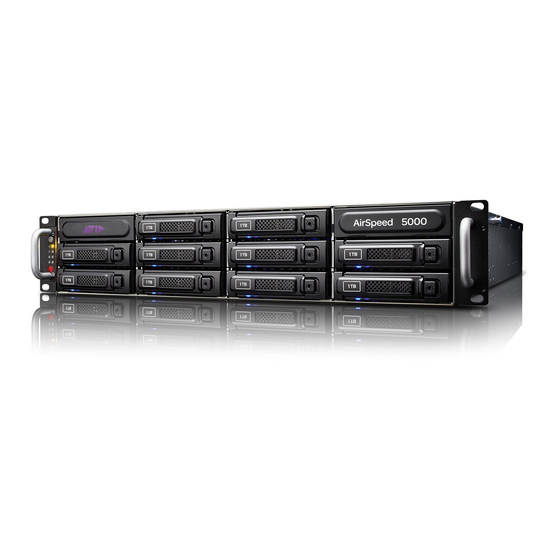
Page 3: Media Drive Verification
• Drive [RAID:Intel Volume0] • Drive [RAID: (Bus 09 Dev 0] 6. Using the arrow keys, move to the exit menu. Select “Save Changes and Exit”. The system will now boot into windows. Media Drive Verification This section covers the procedure used to verify the Media Disks are installed correctly. 1. -
Page 4: Avid Health Monitor
1. The status of the systems temperatures, voltages, motherboard, system fans, hard disk and Avid hardware can be viewed in the Health Monitor. 2. To open the Avid Health Monitor to view the health of the AirSpeed 5000 system. Select Start > All Programs > Avid > Avid Framework > Avid Health Monitor. -
Page 5: Customer Diagnostics Test Setup
• Yellow exclamation point: Warning status. • Red X: Failing (errors) status. Customer Diagnostics Test Setup Installing loopback Cables 1. The VIO (Corona) cards are the top 2 cards in the system (VIO1 (Corona 1) and VIO2 (Corona 2)). As shown in the picture below. -
Page 6: Running The Customer Diagnostics
Running the Customer Diagnostics 1. The AirSpeed 5000 applications starts automatically once the system has completely booted to windows, as shown below. The applications must be disabled before the diagnostics can be started. Do the following: To disable the application from the Application window, select one app at a time. Once the application is selected, the Disable Application button will be enabled, as shown below. - Page 7 2. From the desktop, double click on the Computer Icon. 3. Navigate to C:\Program Files (x86)\Avid\ AirSpeed\Utilities\DiagnosticUtilities Double click AirSpeed5000Test.exe to launch the diagnostics. A Reading HW Information window appears, followed by color bars detailing the diagnostic version. The diagnostics will take about a minute to start. Upon completion, the main diagnostic screen will appear with the information tab displayed as shown below.
- Page 8 6. With loopback cables installed (see installing cable section above), select the loopback tests you want to run as shown below. 7. Select Start. Testing will begin. • The window will update with the following: See picture below. • Incrementing test time •...
-
Page 9: Review The Diagnostic Logs
(x86)\Avid\AirSpeed\ Utilities \DiagnosticUtilities\DIAG_LOG_FILES. Copy and send the .txt (diag log) to Avid for further analysis. Disassembly Process This section covers the procedure used to disassemble the various components of an AirSpeed 5000 system. Hard Disks and Power Supply Removal If an OS and/or media drive fails and needs to be replaced, follow steps 1a and 1b. -
Page 10: Chassis Cover Removal
Chassis Cover Removal To remove the VIO Boards, Expansion Board or the LSI Controller from the system, the chassis cover needs to be removed. 1. Remove the top cover by loosening the 2 thumbscrews. If the screws are too tight, use a Philips head screw driver to loosen the thumbscrews. If the cover is difficult to move, using both palms simultaneously push in and pull the sides backward. - Page 11 Slide up the bracket to remove. 3. Remove the power cables from the 2 VIO cards. 4. View the SATA cable connection between the Expansion (Hydra) and 2 VIO cards as shown below. Remove the cables. To make sure the cables are put back correctly refer to this section when reinstalling.
-
Page 12: System Fan Removal
• There are a total of 7 fans in the AirSpeed 5000 system, 6 are located in the fan bar towards the front of the system and 1 is located in the rear of the chassis by the OS media drive housing.
Need help?
Do you have a question about the AirSpeed 5000 and is the answer not in the manual?
Questions and answers