
Related Manuals for Emerson Rosemount CCO 5500


Summary of Contents for Emerson Rosemount CCO 5500
- Page 1 Reference Manual 00809-0100-4550, Rev AA June 2018 ™ Rosemount CCO 5500 Carbon Monoxide (CO) Analyzer...
- Page 2 1-855-724-2638, and we will provide the requested manual. Save this manual for future reference. • If you do not understand any of the instructions, contact your Emerson representative for clarification. • Follow all warnings, cautions, and instructions marked on and supplied with the product.
- Page 3 WARNING! Highlights an operation or maintenance procedure, condition, statement, etc. that if not strictly observed, could result in injury, death, or long-term health hazards of personnel. CAUTION! Highlights an operation or maintenance procedure, practice, condition, statement, etc. that if not strictly observed, could result in damage to or destruction of equipment or loss of effectiveness.
-
Page 5: Table Of Contents
Contents Contents Chapter 1 Description and specifications ..................1 Component checklist ........................1 Overview ............................3 System description .........................3 Specifications ..........................5 ™ Rosemount CCO 5500 ordering information ................6 Chapter 2 Install ..........................7 Unpack the equipment ........................7 Safety considerations ........................7 Cable requirements ........................8 Selecting location ...........................8 2.4.1 Points to consider ...................... - Page 6 Isolation procedure ......................79 Chapter 5 Maintenance ........................81 Preventative maintenance ......................81 5.1.1 Cleaning windows ......................81 Corrective maintenance ....................... 82 5.2.1 Replace heater element ....................82 5.2.2 Replace chopper motor assembly ..................84 5.2.3 Replace source unit gas cell ................... 86 Rosemount CCO 5500...
- Page 7 Contents 5.2.4 Replace receiver unit gas cell ..................87 5.2.5 Electronics ........................88 Adjust span factor ........................88 5.3.1 Reset span factor ......................89 Chapter 6 Troubleshooting ......................91 Finding faults with the keypad ......................91 6.1.1 Data valid LED out ......................91 Troubleshooting tables ........................
- Page 8 Contents Rosemount CCO 5500...
-
Page 9: Description And Specifications
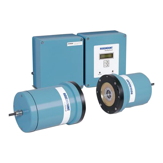
Description and specifications Description and specifications Component checklist ™ A typical Rosemount CCO 5500 Carbon Monoxide Analyzer should contain the items shown in Figure 1-1. Record the part number, serial number, and order number for your system. Reference Manual... - Page 10 33 ft, (10 m) cables Source Gaskets (4) Also, use the product matrix in Section 1.5 to compare your order number against your unit. Ensure the features and options specified by your order number are on or included with the unit. Rosemount CCO 5500...
-
Page 11: Overview
The instrument can achieve temperatures up to 1200 °F (650 °C), but degradation in instrument accuracy will occur. The rugged construction makes installation extremely simple, and through the use use of microprocessor technology, the Rosemount CCO 5500 has many advanced features: • Serial data facility to allow communication between analyzers and a central data logging station. - Page 12 Power supply unit NOTICE The maximum cable length allowed between the power supply and the receiver is 82 ft (25 m). The maximum cable length allowed between the power supply and the transmitter is 33 ft (10 m). Rosemount CCO 5500...
-
Page 13: Specifications
Description and specifications Specifications Table 1-1: System Measurement Specifications Span Selectable 0-100 ppm to 0-10,000 ppm within the range of 200 to 6,000 ppm.m Accuracy ±2% of measurement or ±5 ppm, whichever is greater Path length 1.6 to 26.2 ft. (0.5 to 8 m) Process temperature range 32 to 1202 °F (0 to 650 °C) Display units... -
Page 14: Rosemount Cco 5500 Ordering Information
CCO 5500 ordering information Model Description CCO 5500 Carbon Monoxide Analyzer - across-the-stack Level 1 power requirements 110/220 Vac, 50/60 Hz Level 2 control module display/keypad English Level 3 calibration options None Calibration check cell and holder Rosemount CCO 5500... -
Page 15: Chapter 2 Install
Install Install WARNING! Before installing this equipment, read Essential Instructions. Failure to follow safety instructions could result in serious injury or death. WARNING! ELECTRICAL HAZARD Install all protective equipment covers and safety ground leads after installation. Failure to install covers and ground leads could result in serious injury or death. WARNING! ELECTRIC SHOCK Before making any electrical connections, make sure the AC power supply is first switched off. -
Page 16: Cable Requirements
Flue gas temperatures should not exceed 572 °F (300 °C) at the point of measurment. NOTICE The instrument can achieve temperatures up to 1200 °F (600 °C), but degradation in instrument accuracy will occur. There must be an uninterrupted sight path available between the source and receiver. Rosemount CCO 5500... -
Page 17: Points To Consider
Install The maximum cable length allowed between the power supply and the source is 33 ft. (10 m). The maximum cable length between the power supply and the receiver is 82 ft. (25 2.4.1 Points to consider Path length Too long [> 26 ft (8 m)]: low energy available. Too short [<... -
Page 18: Mount Flange Assemblies
With the stand-off pipes and site mounting flanges welded together, insert the mounting flange assemblies into their mounting holes. Position the mounting flange assemblies so the four threaded mounting holes are located as shown in Figure 2-1. Rosemount CCO 5500... -
Page 19: Isolating Valves
Install NOTICE ™ Rosemount suggests that you tack weld the stand-off pipe to the duct and check the alignment visually before making a complete weld. Look through one of the mounting flange assemblies. If the you can see the orifice across the stack clearly, the alignment is satisfactory. The alignment of these holes is not critical;... -
Page 20: Purge Air Supply
Blower air You may use a blower to provide the air to the air purge. Customers may specify their own blower. The blower should deliver 11 cfm (5 liters/second) per purge against the working pressure of the duct. Rosemount CCO 5500... -
Page 21: Air Purge Units
Install Figure 2-3: Air Purge Mounting Site mounting flange or isolating valve flange Adusting nuts Locking nuts Air purge Rear flange Front flange 2.5.4 Air purge units Use the general procedure that follows to install the air purge units on the site mounting flanges or on the exposed flanges of the customer supplied isolating valves, if used. -
Page 22: Source And Receiver Units
C. Source D. Alignment dowel pin hole E. Threaded screw hole F. Rear face of air purge Attach the source or receiver to the rear face of the air purge and install the four screws provided (Figure 2-5). Rosemount CCO 5500... -
Page 23: Control Unit
Install Figure 2-5: Air Purge and Source Units (Installed) A. Site mounting flange B. Front flange C. Gasket D. Source or receiver E. Window plate F. Air purge G. Rear flange 2.5.6 Control unit ™ Rosemount supplies adequate cableto locate the control unit up to 33 ft. (10 m) from the receiver. -
Page 24: Power Supply Unit
You may use a maximum cable length of 82 ft. (25 m) to connect the power supply unit to the receiver. Do not exceed the 82 ft. (25 m) maximum cable length. Dimensions and mounting hole locations are identical to the control unit and are shown in Figure 2-6. Rosemount CCO 5500... -
Page 25: Electrical Data
Install Electrical data 2.6.1 AC supplies ™ You can power the Rosemount CCO 5500 Analyzer from either 85-135 Vac or 170-264 Vac at 50/60 Hz. A switch within the power supply unit selects the input voltage, and an internal 2 A fuse protects the instrument. The analyzer tolerates voltage fluctuations within these ranges without losing performance. -
Page 26: Electrical Connections
IEC 947. NOTICE To maintain proper earth grounding, ensure a positive connection exists between the transmitter housing and earth. The connecting ground wire must be 14 AWG minimum. Rosemount CCO 5500... -
Page 27: Installation Of Cables
Install NOTICE Line voltage, signal, and relay wiring must be rated for at least 221 °F (105 °C). Make sure that the voltage and frequency of the AC power supply match the required power specifications. NOTICE If metal conduit is used with the power supply unit and/or the source unit, bond the conduit reliably to protective earth. - Page 28 Install Figure 2-7: System Wiring Diagram Rosemount CCO 5500...
- Page 29 Install Figure 2-8: Wiring Connector Locations (Power Supply Board) 110/220 Vac power in Data-valid relay contacts Alarm relay contacts Interconnect cable contacts Reference Manual...
- Page 30 16 through 22. Tighten the cable gland nut. Connect the receiver cable wires to the control board terminals 16 through 22 according to the wiring diagram, Figure 2-7. Do not connect the receiver cable shield wire at the control unit. Rosemount CCO 5500...
- Page 31 Install Install the source cable in the right front cable port of the control unit enclosure. Provide adequate free wire length for making connections to the control board terminals 8 through 12. Tighten the cable gland nut. Connect the source cable wires to the control board terminals 8 through 12 according to the wiring diagram, Figure 2-7.
- Page 32 Install Rosemount CCO 5500...
-
Page 33: Configuration And Startup
Configuration and startup Configuration and startup Introduction You may need two hours or more to configure the instrument, and you need to complete the following tasks: • Power up • Alignment* • Gain adjustment* • Set operating parameters • Calibration* Note *Perform these operations when a clean stack condition exists. -
Page 34: Alignment
Figure 3-1: Power Supply A. AC power selector switch B. Rail indication LED Power up the Rosemount CCO 5500 Analyzer and verify that the power supply rail indication LED (Figure 3-1) lights up. Install and fasten the power supply unit cover. - Page 35 Configuration and startup Figure 2-5. Unscrew the four screws that secure the receiver to the air purge. Remove and place the receiver in a safe location. Go to the source unit location. To align the source, turn the adjusting nuts (Figure 3-2).
- Page 36 When 5 (SET UP) is displayed on the LCD, press ENTER to access the SET UP mode. Note The analyzer uses a security code to prevent unauthorized alteration of settings. The default code set at the factory is 0000. The keypad cursor flashes over the first digit of the security code. Rosemount CCO 5500...
-
Page 37: Detector Levels
Configuration and startup Use the arrow keys to enter the desired value for this digit. Press ENTER to select the displayed value; the cursor moves to the second digit. Select the value for the second digit and press ENTER. Continue this process for each digit of the security code. -
Page 38: Receiver Gain Adjustment
Connect the voltmeter to the test points on the control unit (18/20 for D1 and 19/20 for D2). Increase the gain using the trim pot at the end detector D2 until the voltage is between 1 - 4 Vac. Rosemount CCO 5500... -
Page 39: Control Unit Gain Adjustment
Configuration and startup Repeat Step 5 for the side detector D1 measuring across the test points. When the detector levels are satisfactory, replace the cover. Note If the duct is operating and a high opacity may be in the path, reduce the set voltages to 2 V rms maximum. - Page 40 D2 level is between 12,000 and 15,000. Allow time between adjustments for the readings to settle. Note If the duct is operating and the opacity levels are high, reduce the D2 level to about 8,500. This should prevent saturation should the opacity level drop off. Rosemount CCO 5500...
-
Page 41: Source Adjustments
Configuration and startup To ensure that the detector signal is not saturating, observe the saturation count signal displayed next to the detector levels. If a SAT # of more than 0 is displayed, turn the trim pot slightly to reduce the gain. Reduce the gain until a SAT # of 0 is displayed. -
Page 42: Chopper Frequency
Unscrew and remove the source from the air purge. Unscrew and pull the window plate from the front of the source unit. Figure 3-7. A trim pot (VR1) allows you to adjust the frequency of the chopper motor. Rosemount CCO 5500... -
Page 43: Set Up Mode
Configuration and startup Figure 3-7: Chopper Frequency Trim Pot A. Trim pot VR1 To increase the chopper frequency, turn the trim pot counterclockwise. Set up mode To prevent any unauthorized changes, you must enter a four digit security code to enter the set up mode. -
Page 44: Enter Security Code
The instrument calculates four separate averages. These are defined in units of seconds, minutes, hours, and days. You can use any of the four averaging stacks to provide the instrument's analog output. You can set each averaging time within predefined limits. Rosemount CCO 5500... -
Page 45: Configure O/P
Configuration and startup Press ENTER when this display is shown. The display now shows one of the averages. Use the arrow keys to select the average time that you need to change and press ENTER to change it. You can now change the value using the arrow keys and confirm it by pressing ENTER. - Page 46 Select the required span using the arrow keys for each digit. Press ENTER to enter the value of each digit. The units are displayed in vpm, mg/m , or mg/Nm , depending on what has been selected beforehand. Rosemount CCO 5500...
- Page 47 Configuration and startup Note Once you select Output Span, the current value is displayed for one second. The first digit of the display then defaults to zero; thus you must re-enter the span value for the unit to function correctly. Fault condition If a fault condition occurs, you may set the current output of the instrument to one of the following options:...
-
Page 48: Parameters
Select each digit with ENTER and change it with the arrow keys. Note It is important to make note of this number; otherwise, it will not be possible to change the instrument set up. Rosemount CCO 5500... - Page 49 Section 2.4.1. The Rosemount CCO 5500 Analyzer is sensitive to the product of concentration and path length. In order to obtain a true value of concentration of gas, you must input the correct path length into the processor. The processor then uses the value to produce a final value of gas concentration.
- Page 50 (e.g., a value that opens and closes the duct). Press ENTER to select this option when the Plant Status → Serial Input option is displayed. • Serial input Rosemount CCO 5500...
-
Page 51: Normalization
Configuration and startup If you select this option, the criteria controlling plant status are transmitted via the serial data link. Press ENTER when the Plant Status I/P → Serial Input option is displayed to select this option. • Multiple Four options are available here. Press ENTER when the Plant Status I/P → Multiple option is displayed, and the first option Temperature is displayed. - Page 52 Press ENTER with the Temperature option selected to access Set Standard Levels and Set Values. Use the arrow keys to toggle between these options and Exit. Set Values You can bring the normalizing data into the instrument in one of three ways: • Analog Input Rosemount CCO 5500...
- Page 53 Configuration and startup This uses the 4-20 mA inputs within the processor to receive the measured transducer data. The values at 4 mA and 20 mA will be requested should this option be selected. • Serial Input If you use an input unit, all normalizing data can be transmitted via the serial data line.
-
Page 54: Reset Averages
While in this mode, the gas cell is not moved; this gives an immediate response for setting up the detector levels. A Cal Factor that is calculated during a calibration routine sets the basic calibration of the instrument. Press ENTER while this is displayed to see the following options: Set Detectors Rosemount CCO 5500... - Page 55 Configuration and startup Span Adjust Calibrate Set detectors You can display both the D1 and D2 levels; you can also display saturation counts. To give an immediate response to any alterations that are required, the filters and gas cells are not moved during this operation.
- Page 56 Table 3-1 lists all of the options available and can be used as a record of the operating parameters. Table 3-1: Instrument Settings Parameter Config Averages Seconds Minutes Hours Days Output 0 or 4 mA base Units Average Rosemount CCO 5500...
- Page 57 Configuration and startup Table 3-1: Instrument Settings (continued) Parameter Config Fault condition Parameters Path length Alarm source Alarm units Alarm levels Normalization Temperature Standard level °F (°C) I/P °F (°C) @ 4 mA I/P °F(°C) at 20 mA Keypad input °C (not ideal) Serial input Oxygen Standard level %...
-
Page 58: Current Output Calibration
3-2. Enter Mode 5 → Configure Output → Fault Condition → Set Span and adjust the level using the arrow keys until 20 mA is recorded. Record the value in brackets on the display in Table 3-2. Rosemount CCO 5500... -
Page 59: Chapter 4 Operation
The Rosemount CCO 5500 Analyzer allows you to interrogate the microprocessor to observe the system parameters and to change them if required. The Rosemount CCO 5500 uses a menu-based program; you can gain access to it by the key panel mounted on the lid of the control unit (Figure 4-1). -
Page 60: Calibration
Mode 5: Set up Mode Sets operating parameters. You must enter the opening parameters for the instrument to function correctly. You can only access this mode using a security code. Rosemount CCO 5500... -
Page 61: Keypad Operation
Operation Mode 6: Check Cell Mode Used to verify the instrument's operation and calibration. Note The outputs of the instrument are unaffected by key operation in all modes except the Set up mode. Keypad operation You can access each mode sequentially by each push of the MODE key. Figure 4-1 illustrates the display and keys of the control unit. - Page 62 Operation Figure 4-2: Rosemount CCO 5500 Analyzer Menu Tree Operating mode vpm, mg/m mg/Nm Measure, Normalized, Sec, Min, Hour, Parameters Identification Analyzer type EPROM program ID Identity number Parameters Path length Span factor O/P fault Averages Sec, Min, Hour, Day...
-
Page 63: Operating Mode
Operation Set up mode Parameters Security 4 digit code Identity 01 to 30 Path length Gas path length in mm Source Sec, Min, Hour, Day Alarm Units Vpm, mg/m , mg/Nm Alarm level (0 to 9999) Cal. factor 0 to 9999 Plant St. -
Page 64: Parameters
Use the arrow keys to scroll between these options. 4.7.2 Parameters You can display the following parameters from this option; select them using the arrow keys. Path Length: The path length currently used to calculate the gas calculation. Rosemount CCO 5500... -
Page 65: Averages
Operation Span Factor: You can adjust the sensitivity of the instrument from the SET UP mode → CALIBRATE option. Rosemount ™ initially set the span factor at the factory using known gas concentrations. O/P (Output) Fault: Should a fault condition occur, you can set the analog input from one of four options. -
Page 66: Diagnostic Mode
Calibration Data Fault Conditions 4.9.1 Detector outputs This mode displays detector levels from the detector. D1 is the reference level and should always be less than D2. The level of D2 should be between 10,000 and 20,000. Rosemount CCO 5500... -
Page 67: Modulation (Chopper Motor) Frequency
Operation E1 and E2 are the detector levels with the gas cell within the source unit in the sight path and will be roughly ½ of the D2 and D1 levels. The analyzer may also display smoothed detector values; these are noted as d1, d2, e1, and e2. Sat. -
Page 68: Calibration Data
Cal. Fact. O.R.: After the calibration routine, the calculated Set Cal factor is out of range. Refer to Chapter Press the arrow key to observe the previous fault condition. Note If a fault condition exists, the instrument does not update the minutes, hours, and days averages. Refer to Section 6.1.1. Rosemount CCO 5500... -
Page 69: Set Up Mode
Operation 4.10 Set up mode You can change all operating parameters (averaging times, output settings, normalization parameters, path length, calibration, etc.) from this mode. To prevent any unauthorized changes, you must enter a four digit code before you can enter this mode. Note After you select this mode, the instrument suspends its operation and extinguishes the Data Valid ™... -
Page 70: Set Averages
This is limited to within 1 to 60 minutes in 1-minute intervals. Set the hours averaging stack to the required value. This is limited to within 1 to 24 hours in 1-hour intervals. Set the days averaging stack to the required value. Rosemount CCO 5500... -
Page 71: Configure O/P
Operation This is limited to within 1 to 30 days in 1-day intervals. 4.10.3 Configure O/P You can set up the analog loop output from this mode. Press ENTER while this display is shown to access it. Press the arrow keys to step through the available options. Press ENTER to access and change the displayed parameters of each of the six available options listed below: a. - Page 72 Press the arrow keys to select one of these options; when the desired output is displayed, press ENTER to confirm. Set mA output Note This is set at the factory and should not be altered without due consideration. Rosemount CCO 5500...
-
Page 73: Parameters
Operation From this option, the current levels of the analog output are set up. Press ENTER to select it, and the instrument prompts you to set the current levels at 0 and 20 mA. When this is displayed, set the current output to 0 mA as measured with a calibrated current meter across the analog ouput loop terminals;... - Page 74 Section 2.4.1. The Rosemount CCO 5500 Analyzer is sensitive to the product of concentration and path length. In order to obtain a true value of concentration of gas, you must input the correct path length into the processor. The processor then uses the value to produce a final value of gas concentration.
- Page 75 Operation Alarm A contact output is available to warn of a high gas concentration. You may trigger the contact output from any of the four averaging stacks. Select the source with the arrow key and enter it with ENTER. Select the units for the alarm; these may be different than the units selected for the analog output.
- Page 76 Oxygen is set and used in a similar manner to the temperature threshold. However, if the normalizing oxygen level rises above the threshold, plant status is OFF. For plant status ON, the oxygen level must be below the threshold. Water Vapor Rosemount CCO 5500...
-
Page 77: Normalization
Operation This is set and used in a similar manner to the temperature threshold. If the normalizing water vapor level falls below the threshold, plant status is OFF. For plant status ON, the water vapor level must be above the threshold. Logic Input Select YES or NO and press ENTER. - Page 78 If the oxygen level is being continuously measured, connect ™ the analog output of the oxygen analyzer into the Rosemount CCO 5500 Analyzer and select Analog Input. You must define this input as either WET or DRY depending on how the Rosemount CCO 5500...
-
Page 79: Reset Averages
Operation measurement is made. After you define the wet or dry, you need to define the Analog Input values; set the 4 mA and 20 mA values. If the oxgyen level is relatively constant through all firing conditions, you may use a fixed keypad input. With an integrated system, you can take the oxygen data to the instrument via the serial data line. -
Page 80: Calibrate
Span adjust Note ™ Rosemount initially sets the span factor at the factory; do not adjust it unless the instrument sensitivity is suspected. In any case, Rosemount recommends that you record the orginal value before making adjustments. Rosemount CCO 5500... - Page 81 Operation You can adjust instrument sensitivity if a known concentration of gas exists between the source and receiver units and instrument sensitivity is supsected. If a problem arises, consult Rosemount. You may need to adjust the span factor if you have fitted new gas cells or filters. Calibrate Re-enter the Mode 5 CALIBRATE menu and proceed to the Calibrate option.
- Page 82 I/P °F (°C) @ 4 mA I/P °F(°C) at 20 mA Keypad input °C (not ideal) Serial input Oxygen Standard level % Wet or dry gas I/P % @ 4 mA I/P % @ 20 mA Keypad input % Serial input Rosemount CCO 5500...
- Page 83 Operation Table 4-1: Instrument Settings (continued) Parameter Config Pressure Standard level psi (kPa) I/P psi (kPa) @ 4 mA I/P psi (kPa) @ 20 mA Keypad input Serial input Water vapor Standard level (wet %/dry Keypad input % Measured value After the calibration is conducted, a cal factor is calculated;...
-
Page 84: Check Cell Mode
The check cell and holder are optional items available from Rosemount. Rosemount has designed the check cell to verify the reading of Rosemount cross duct analyzers. When placed within the measurement path, the check cell can generate a known increase in gas concentration. Rosemount CCO 5500... - Page 85 Operation Prerequisites Note Place the check cell at the receiver side. Measurement conditions For absolute verification, you must check the instrument when no measurement gas is present. If a background concentration of measurement gas is present, an increase will still be generated, but the net effect will be complex.
- Page 86 Remove the check cell and wait for the analyzer to return to zero (another five to ten minutes). Replace the cover on the check cell holder and place MODE on the control unit. The instrument now returns to OPERATING mode. Rosemount CCO 5500...
-
Page 87: Alarms And Emergency Conditions
Do not insert the check cell in any other mode as this will influence the recorded rolling averages. Rosemount fixes the calibration of the Rosemount CCO 5500 Analyzer at the point of manufacture. If gross errors exist, this could suggest an instrument malfunction. If you observe minor errors, please check the procedure and if necessary, return the gas cell for recertification. - Page 88 Operation Rosemount CCO 5500...
-
Page 89: Chapter 5 Maintenance
Maintenance Maintenance Preventative maintenance Rosemount designs this equipment to keep maintenance to an absolute minimum. 5.1.1 Cleaning windows It is important that you keep the optical windows of both the source and receiver reasonably clean. Keep any mounting tubes free from build-up of dust and fly ash. Clean the optical window (Figure 5-1) every six months and more frequently for dirty... -
Page 90: Corrective Maintenance
Replace a failed heater element according to the following procedure. Procedure Shut down and lock out power to the Rosemount CCO 5500 Analyzer. Unbolt and remove the source unit from the air purge. Loosen the source unit cable gland... - Page 91 Maintenance Figure 5-3: Source Unit Circuit Board A. Circuit board mounting screw B. Circuit board Remove the terminal nuts (Figure 5-4) and remove the heater wires. Figure 5-4: Heater Element A. Terminal nuts B. Captive screw C. Heater Unscrew the three captive screws. Remove and discard the heater assembly.
-
Page 92: Replace Chopper Motor Assembly
Install the circuit board and retaining screws removed in Step Install and fasten the rear cover plate. Power up the Rosemount CCO 5500 Analyzer and allow fifteen minutes for the heater to reach operating temperature. The analyzer starts to monitor the gas levels. - Page 93 Secure the source unit to the air purge using the four screws removed in Step Tighten the screws evenly. Power up the Rosemount CCO 5500 Analyzer and check the chopper motor frequency in Mode 4 (DIAGNOSTICS). Adjust using the trim potentiometer as described in Section 3.6.
-
Page 94: Replace Source Unit Gas Cell
Install the center plate and circuit board assembly and secure with the three brass screws removed in Step Line up and install the window plate onto the source unit. Fully seat the window plate flange in the source unit. Rosemount CCO 5500... -
Page 95: Replace Receiver Unit Gas Cell
Maintenance Secure the source unit to the air purge using the four screws removed in Step Tighten the screws evenly. Power up and recalibrate the Rosemount CCO 5500 Analyzer. Refer to Calibrate. 5.2.4 Replace receiver unit gas cell Replace the receiver unit gas cell according to the following procedure. -
Page 96: Electronics
Secure the receiver unit to the air purge using the four screws removed in Step Tighten the screws evenly. Power up and recalibrate the Rosemount CCO 5500 Analyzer. Refer to Calibrate. 5.2.5 Electronics The electronics require no routine maintenance. They are all solid state and undergo a rigorous factory burn-in procedure. -
Page 97: Reset Span Factor
Maintenance Procedure At the control unit keypad, select Mode 5 → Configure O/P → Set Span. Set the span factor to 1000. Calibrate the analyzer under zero conditions. Refer to Calibrate. Select Mode 5 → Normalization. Set the temperature to 68 °F (20 °C). Select Mode 5 →... - Page 98 Maintenance Rosemount CCO 5500...
-
Page 99: Chapter 6 Troubleshooting
Troubleshooting Troubleshooting Finding faults with the keypad WARNING! ELECTRIC SHOCK Install all protective equipment ground covers and safety ground leads after troubleshooting. Failure to install covers and ground leads could result in serious injury or death. If a fault occurs, the control unit display switches from its current mode of operation to the DIAGNOSTICS mode and displays the current fault condition. -
Page 100: Troubleshooting Tables
"proceed to next possible cause" are indicated. The troubleshooting tables indicate which of the four units failed: • Source unit • Control unit • Receiver unit • Power supply unit ™ You can then return the faulty unit to Rosemount for repair. Rosemount CCO 5500... - Page 101 Troubleshooting Table 6-2: Configuration Problems Possible cause Test Result Action No display on control unit Power input failure Check 110/220 V selection Setting correct Go to next test. switch. Setting incorrect Change setting and go to next test. Check power indication LED LED illuminated Power OK - go to next possi- in control unit.
- Page 102 Incorrect gain settings Adjust gain settings in con- Saturation clears. No further action. trol unit and/or receiver Fault continues. Go to next test. unit. Monitor detector levels Signal OK No further action from receiver unit. Signal faulty Contact Rosemount. Rosemount CCO 5500...
- Page 103 Troubleshooting Table 6-2: Configuration Problems (continued) Possible cause Test Result Action Modulation frequency out of range Chopper motor speed out of Adjust chopper motor Modulation frequency in No further action range speed. range Unable to adjust Go to next test. Monitor reference wave- 30 - 45 Hz waveform OK form across test points 10...
-
Page 104: Component Tests
Complete the following steps to check the analyzer's chopper motor. ™ Power up the Rosemount CCO 5500 Analyzer. Observe the chopper motor and blade between the lens and heater cartridge. If the blade is spinning, the chopper motor is OK. Rosemount CCO 5500... -
Page 105: Led Indications
Troubleshooting If the blade is not spinning, measure the supply to the chopper motor voltage at the test points M+ and M- on the circuit board (Figure 5-5). The voltage should read approxmately 1 Vdc. If the voltage is good, replace the chopper motor. -
Page 106: Test Points
33.8 °F (1 °C). Normalizing input for pressure before A/D con- verter 0.8 to 0.4 V = 4 to 20 mA. As T8 except oxygen. As T8 except temperature. +5 and 0 V Supply rails for micro-processor. DC voltage. Rosemount CCO 5500... - Page 107 Troubleshooting 12 V Suppy rail for the plant status input. +15 V, -15 V, and 0 VA Supply rails for the analog current output. Output from the D/A converter. 0 to 2.5 V repre- sents 0 to 20 mA (4 mA at 0 V). -15 V1, 0 V, and +15 V1 Isolated supply for the analog current output.
- Page 108 Troubleshooting Rosemount CCO 5500...
-
Page 109: Chapter 7 Spare Parts
Below are typical spares that you should consider. Table 7-1: Rosemount CCO 5500 Analyzer Recommended Spare Parts Part number Description 1A99995H01... - Page 110 Spare parts Rosemount CCO 5500...
-
Page 111: Appendix A Theory Of Operation
Theory of operation Appendix A Theory of operation Infrared source unit At the heart of this unit is a small heater assembly designed to give a high intensity uniform source of infrared energy. The heater assembly can provide in excess of two years of continuous operation with a power consumption of only 26 watts. -
Page 112: Infrared Receiver Unit
They respond only to changing levels of radiation and thus to the chopped radiation from the infrared source unit and not to the background radiation from the flue or flue gas. The detector signals are amplified and fed to the control unit. Rosemount CCO 5500... -
Page 113: Control Unit
Theory of operation Control unit The control unit is a housed in a fully-sealed cast-aluminum enclosure. It houses the microprocessor to monitor the data from the receiver and produces a 4-20 mA output signal for gas levels within the flue. A non-volatile RAM section, requiring no battery back-up, enables all of its operation data to be retained during a power down condition. -
Page 114: Principles And Modes Of Operation
CO in the sight path and measures the two detector outputs again to give readings E1 and E2. From the basic scale shape equation: Y = G - K (D1/D2) and from the calibration equation: = G - K (E2/E1) or K = (G - Y )(E1/E2) Rosemount CCO 5500... -
Page 115: Calculation Sequence
. The following paragraphs describe the derivation of these results. The Rosemount CCO 5500 Analyzer is a cross-duct type that measures the quantity (number of molecules) of gas within its sight path. It converts this measurement into a concentration that fully compensates for the expansion effects of temperature, while assuming constant atmospheric pressure. - Page 116 = %O measured When no correction is required for water vapor: O = 0 After the instrument has performed all calculations, the resulting measurement is the effective mass concentration (mg/Nm ) of the pollutant normalized to standard conditions. Rosemount CCO 5500...
-
Page 117: Principles Of Cross-Duct Gas Analyzers
Theory of operation Measured conditions Where measured values are required (e.g., to calculate rates of emissions) they need to be recalculated for measured temperature and pressure using the equation: by substituting the correction for standard pressure: the measured mass concentration of the CO gas is: A.7.5 Principles of cross-duct gas analyzers Cross-duct analyzers work on the basic principle that infrared (IR) energy is absorbed by... - Page 118 Transmissivity of CO within the 4.7 µm band The concentration of CO affects the IR energy's transmission through the gas at about 4.7 µm. Figure A-4 illustrates how the energy within the selected band varies with CO concentration. Rosemount CCO 5500...
- Page 119 (in meters) over which it has been measured. Carbon monoxide calculation The Rosemount CCO 5500 Analyzer takes two measurements of IR energy in the narrow band around 4.7 µm. It takes both measurements after the beam has passed through the gas to be measured.
- Page 120 CO. Well designed cross-duct analyzers introduce this gas cell every few seconds to continuously check and (if necessary) modify the zero position. Rosemount CCO 5500...
-
Page 121: Appendix B Return Equipment To The Factory
You must return equipment with complete identification in accordance with ™ Rosemount instructions or Rosemount will not accept it. In no event, will Emerson be responsible for equipment returned without proper authorization and identification. Carefully pack defective unit in a sturdy box with sufficient shock absorbing material to ensure that no additional damage will occur during shipping. - Page 122 Return equipment to the factory Rosemount CCO 5500...
- Page 123 Return equipment to the factory Reference Manual...
- Page 124 2018 Emerson. All rights reserved. youtube.com/RosemountMeasurement The Emerson logo is a trademark and service mark of Emerson Electric Co. Rosemount is a google.com/+RosemountMeasurement mark of one of the Emerson family of companies. All other marks are the property of their AnalyticExpert.com respective owners.
Need help?
Do you have a question about the Rosemount CCO 5500 and is the answer not in the manual?
Questions and answers