Table of Contents
Advertisement
®
Owner's Manual and Assembly Instructions
Model #: W348AC-P-F
Read and understand the entire manual before assembly and operation. The vehicle must be
assembled by an adult who has read and understands the instructions.
Made in China.
Styles and colours may vary. Do not return to store. Call 1-888-982-9309 for assistance and
replacement parts.
IMPORTANT:
Save this manual with your sales receipt.
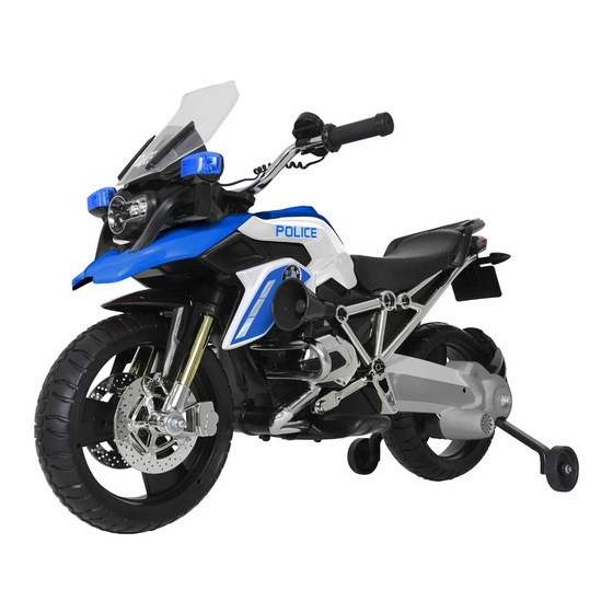
6V BMW Police Motorcycle
Advertisement
Table of Contents

Related Manuals for Rollplay W348AC-P-F


Summary of Contents for Rollplay W348AC-P-F
- Page 1 6V BMW Police Motorcycle ® Owner’s Manual and Assembly Instructions Model #: W348AC-P-F Read and understand the entire manual before assembly and operation. The vehicle must be assembled by an adult who has read and understands the instructions. Made in China.
- Page 2 Introduction Thank you for purchasing this Rollplay vehicle. We hope the rider enjoys it for miles to come. Please read this instruction guide carefully before assembling and operating the vehicle. Please have your model number and serial number ready before calling. Please have proof of purchase.
- Page 3 Call Customer Service if you need assistance or replacement parts. Please have your model number and serial number ready before calling. Please have proof of purchase. Keep your sales receipt and register your product at www.rollplay.com as we may require proof of purchase. 1-888-982-9309 Read this entire manual to ensure proper assembly and safe operation of the vehicle.
- Page 4 This page has intentionally been left blank.
-
Page 5: Table Of Contents
Table of Contents Safety ..............6 Parts ..............8 Charging Instructions ......... 9 Assemble the Front Wheel ........ 10 Assemble the Rear Fork ........11 Assemble the Rear Wheel ......... 12 Assemble the Support Wheels ......13 Attach the Mud Guard ........14 Attach the License Plate ........ -
Page 6: Safety
Safety WARNING: SAFETY RIDING RULES The user must follow all safety rules and guidelines, or serious injury or death may occur. • Always use common sense and safe practices when using the vehicle. The user must be at least 3 years old and weigh no more than 35 kg (77 lb). •... - Page 7 Safety (Continued) WARNING: BATTERY SAFETY • Battery posts, terminals and related accessories contain lead and lead compound (acid) chemicals known to the state of California to cause cancer, reproductive harm, and are toxic and corrosive. DO NOT open the battery. •...
-
Page 8: Parts
Parts 1. Manual 17. Washers (x5) 31. Gear Box 2. License Plate 18. Wrench 32. Microphone 3. Baggage Rack 19. Hexagon Nut (x4) (on axles) 33. Siren Lights 4. Rear Mud Guard 20. Battery 34. Megaphone (located under the seat) 5. -
Page 9: Charging Instructions
Charging Instructions YOU MUST CHARGE THE BATTERY FOR 24 HOURS BEFORE THE FIRST USE! CHARGE THE BATTERY ONCE A MONTH, EVEN WHEN NOT IN USE! ONLY AN ADULT SHOULD HANDLE THE BATTERY AND CHARGER. To Charge the Battery: 1. Ensure the vehicle is stopped and turned off. -
Page 10: Assemble The Front Wheel
Assemble the Front Wheel 1. Gently ip the motorcycle over. 2. Slide a brake (13) onto a front fork. 3. Place front tire (14) in between the two front forks and the brake. hole on front fork 4. Insert the front axle (16) through the front fork, front brake and halfway through the tire. -
Page 11: Assemble The Rear Fork
Assemble the Rear Fork Left Right 1. Align the slot on the rear wing bracket (5) with the inner side of the rear, left fork. 2. Insert a self-tapping screw (22) through the wing bracket (5) and into the rear fork to secure. -
Page 12: Assemble The Rear Wheel
Assemble the Rear Wheel View is from back of the motorcycle Left Right 1. Insert the rear axle (30) into the left hole of the rear fork. Do not slide all the way through. 2. Slide the gear box (31) onto the rear axle. Connect the white connector on the gear box with the white engine connector. -
Page 13: Assemble The Support Wheels
Assemble the Support Wheels View is from back of the motorcycle 1. Slide the left support wheel (7) onto the left side of the rear axle. 2. Slide the right support wheel (27) onto the right side of the rear axle. 3. -
Page 14: Attach The Mud Guard
Attach the Mud Guard 1. Align the slot on the back of the mud guard (4) with the back of the rear wing bracket (5). 2. Snap the mud guard onto the rear wing bracket. -
Page 15: Attach The License Plate
Attach the License Plate 1. Align the top of the license plate (2) with the slot on the bottom of the back of the motorcycle body. 2. Slide the license plate onto the slot until it snaps into place. -
Page 16: Assemble The Handle Bars
Assemble the Handle Bars 1. Remove the screw (26) and nut (24) from the steering rod. 2. Slide the handle bars (9) onto the steering rod. Ensure the holes on the handle bars align with the holes on the steering rod. Note: The Power Button should be on the front of the handlebar. -
Page 17: Assemble The Windshield
Assemble the Windshield 1. Connect the corresponding windshield wire to the handlebar wire, then connect the other windshield wire to the motorcycle wire. 2. Align the windshield (10) with the slots on the wire compartment and snap into place, taking care not to damage the wires in the process. -
Page 18: Assemble The Baggage Rack
Assemble the Baggage Rack Using a athead screw driver, turn the seat lock to the unlocked position. 2. Remove the seat (6) by lifting on the back of the seat. 1. Align the front bar of the baggage rack (3) with the gap on the rear of the battery compartment and snap into place. -
Page 19: Attach The Exhaust Pipe
Attach the Exhaust Pipe 1. Align the top and front of the exhaust pipe (21) with the slots on the right side of the motorcycle body and snap into place. 2. Use a self-tapping screw (22) to secure. -
Page 20: Attach The Megaphone And Searchlight
Attach the Megaphone and Searchlight 1. Align the left round tube (36) with the holes on the motorcycle body. The short side should be on top. Slide the tubes in and repeat on the other side, with the right round tube (37), but with the long side on the top. -
Page 21: Attach The Megaphone Speaker
Attach the Megaphone Speaker Jack for microphone 1. Slide the buckle on the back of the microphone (32) into the holster on the handlebar (9). 2. Plug the microphone into the jack, located under the dashboard. -
Page 22: Product Features
Product Features Turn Accelerator to Move Forward ON/OFF Button Sound Button battery for 8-12 hours each additional recharge. 2. ON/OFF Button: Press the ON/OFF Button on the front of the motorcycle dashboard to turn ON the motorcycle. The motorcycle will make a revving noise when it is turned ON. -
Page 23: Maintenance
Maintenance Important Battery and Charger Information • Only an adult who has read and understands the safety warnings may handle and operate the battery and battery charger. Keep away from children. • time. • Recharge the battery immediately after each use. Charge for at least 8-12 hours, but no more than 20 hours. -
Page 24: General Care
General Care • Regularly inspect all vehicle parts to ensure they are in good working condition. • Regularly inspect the charger, cord, plug, and other related parts for damage. • Remove any damaged parts and immediately contact Customer Service for replacement parts. See Service and Repairs on page 28 for more information. -
Page 25: Troubleshooting Guide
Troubleshooting Guide Completely read through the manual and troubleshooting guide before contacting Customer Service. Problem Potential Cause Solution Vehicle does not run Battery is low Recharge the battery Snap pins are loose Tighten snap pins Loose wires or loose Ensure the battery connectors connectors are securely attached. - Page 26 Problem Potential Cause Solution Vehicle needs a push to Loose wires or loose Ensure the battery connectors start connectors are securely attached. If wires are loose, contact Customer Service “Dead spot” on motor A “dead spot” means electricity is not being delivered to the terminal.
-
Page 27: Fcc Information
FCC Information This device complies with part 15 of the FCC Rules. Operation is subject to the following two conditions: (1) this device may not cause harmful interference, and (2) this device must accept any interference received, including interference that may cause undesired operation. This equipment has been tested and found to comply with the limits for a Class B digital device, pursuant to Part 15 of the FCC Rules. -
Page 28: Service And Repairs
Hours: 9 AM - 5 PM (CST), Monday - Friday 888-982-9309 Phone: 1- Email: customerservice@rollplay.com Web: www.rollplay.com For a list of available replacement parts, please visit www.rollplay.com WE WILL REQUIRE PROOF OF PURCHASE. Please save your sales receipt and register your product at www.rollplay.com. -
Page 29: Warranty
This warranty does not cover, and is not intended to exclude any liability on the part of Rollplay, whether under this warranty or implied by law for any indirect or consequential damages for breach of warranty. Some states may not allow the exclusion or limitation so this limitation may not apply to you. -
Page 30: Product Registration
1131 W Blackhawk St. Second Floor Chicago, IL 60642 OR ll out the form online at www.rollplay.com and keep a copy of your sales receipt. We will use the information provided only for your warranty. We will not sell, rent or share your personal information.
Need help?
Do you have a question about the W348AC-P-F and is the answer not in the manual?
Questions and answers