User Manuals: burkert 8791 REV.2 Positioner
Manuals and User Guides for burkert 8791 REV.2 Positioner. We have 3 burkert 8791 REV.2 Positioner manuals available for free PDF download: Operating Instructions Manual, Quick Start Manual
Burkert 8791 REV.2 Operating Instructions Manual (81 pages)
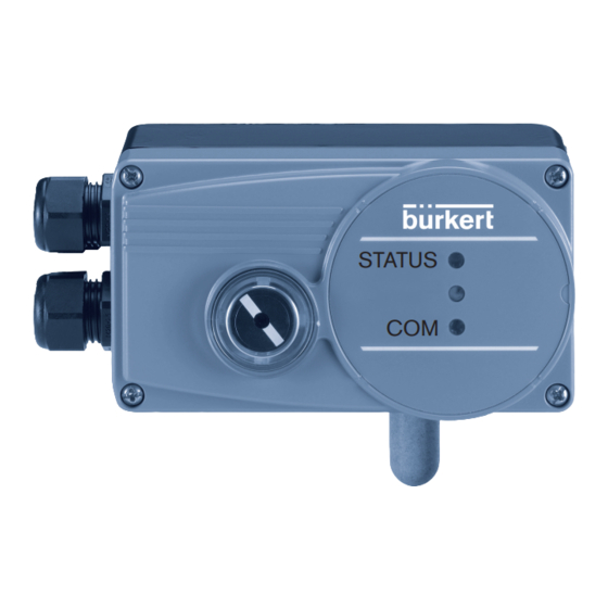
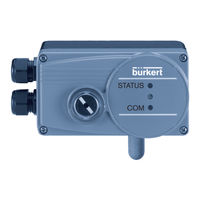
Positioner SideControl BASIC
Brand: Burkert
|
Category: Control Unit
|
Size: 6 MB
Table of Contents
Advertisement

Burkert 8791 REV.2 Operating Instructions Manual (77 pages)
Positioner SideControl BASIC Electropneumatic positioner
Brand: Burkert
|
Category: Valve Positioners
|
Size: 2 MB
Table of Contents

burkert 8791 REV.2 Quick Start Manual (40 pages)
Positioner SideControl BASIC
Brand: burkert
|
Category: Valve Positioners
|
Size: 1 MB
Table of Contents
Advertisement