Advertisement
2 WIRE INTERCOM SYSTEM
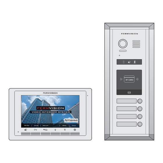
FVI-7004 KIT & FVI-7008 KIT
Quick Guide
RF CARD
RF CARD
FVI-7013
FVI-7014
FVI-7018
Please read this manual carefully before using the product you purchase, and keep it well for future use.We reserve the right to
modify the specification in this manual at any time without notice.
-1-
Advertisement
Table of Contents

Related Manuals for Fermax FVI-7008 KIT


Summary of Contents for Fermax FVI-7008 KIT
- Page 1 2 WIRE INTERCOM SYSTEM FVI-7004 KIT & FVI-7008 KIT Quick Guide RF CARD RF CARD FVI-7013 FVI-7014 FVI-7018 Please read this manual carefully before using the product you purchase, and keep it well for future use.We reserve the right to...
- Page 2 1*4 Branch Controller- FVI-6011DBC4A ; 1*Power Supply- FVI-6017PC6 ; 1*Power cable ; 4*Proximity Cards ; 2*Management Cards- Add Card & Delete Card. FVI-7008 KIT consists of : 1*Outdoor Station- FVI-7018 ; 1*Surface Box- FVI-7000 ; 8*Indoor Unit- FVI-7013; 2*4 Branch Controller- FVI-6011DBC4A;...
-
Page 3: System Connection
2. System Connection 1 pcs FVI-7014 with 4 pcs FVI-7013 FVI-7013 FVI-7013 FVI-7013 FVI-7013 EXTEND EXTEND EXTEND EXTEND EXT-RING EXT-RING EXT-RING EXT-RING Indoor Monitor Indoor Monitor Indoor Monitor Indoor Monitor Room Code = 04 Room Code = 03 Room Code = 02 Room Code = 01 M/S = Master-0 M/S = Master-0... - Page 4 1 pcs FVI-7018 with 8 pcs FVI-7013 FVI-7013 FVI-7013 FVI-7013 FVI-7013 EXTEND EXTEND EXTEND EXTEND EXT-RING EXT-RING EXT-RING EXT-RING Indoor Monitor Indoor Monitor Indoor Monitor Indoor Monitor Room Code = 08 Room Code = 07 Room Code = 06 Room Code = 05 M/S = Master-0 M/S = Master-0 M/S = Master-0...
-
Page 5: Parts And Functions
3. Parts and Functions Microphone LCD Screen Speaker Talk/Mon Button Setup Button Unlock Button Down/Decrease Button Call Button/ Up/Increase Button Unlock 2nd Button Mounting Hook Connection Port 1 2 3 4 5 6 Mounting Hook Key functions Microphone Receive voice from the user. LCD screen Display the visitors' image. - Page 6 Speaker Camera Lens Night View LED Microphone 1 2 3 4 5 6 L1 L2 Status Indicator Connection ID Card Window port RF CARD LED Indicator Nameplate Call button 123 mm Mounting box for Rainy cover for flush mounted surface mounted Note:Key A and key B will not be seen on the panel,they are cryptic.About activating key A and key B, please refer to Part 5.
- Page 7 5. DIP Switches Settings Of Outdoor Station Totally 6 bits can be configured by dip-switch. All ON(1) OFF(0) switches can be modified either before or after installation, please restarting the power whenever the switches have been modified. Bit definition Bit state Function Descriptions Default setting, ID = 0, setting for the first door station 3 4 5 6...
- Page 8 6. Indoor Unit Parameter Setting How to enter the installation setting page 00.00 00.01.00 [ 0000 ] AUTO Exit Exit Next 1.Press About button on 2 . P r e s s a n d h o l d 3.Use button to main menu page.
- Page 9 DIP Switches Settings Of Indoor Unit In the DT system,every apartment must have a unique identification called User Code. The DIP swiches are used to configure the User Code for each Monitor. Bit-1 to Bit-5 are used to User Code setting. The value is from 1 to 32, which have 32 •...
- Page 10 7. Call codes The door station automatically assigns the call codes to the connected module’s buttons. Regardless of the structure of the call button module, the button numbers are listed from the top to bottom and from left to right (in the case of double row buttons): In the case of double row buttons: RF CARD • DIP3 switch set to off...
-
Page 11: Basic Door Release Operation
8. Basic Door Release Operation Press CALL button on outdoor station, the Monitor 00:30 rings, at the same time, the screen displays the visitors' image. Press TALK/MON Button on monitor, you can communicate hands free with the visitor for 90 seconds. After finishing communication, press TALK/MON button again to end the communication. -
Page 12: Specification
Power-off-to-Unlock type: Power-off-to-Unlock type: 12V 300mA Cut off the line +12V LK - +12V LK - (GND) N.O. LK+(COM) N.O. Exit button Exit button 1 2 3 1 2 3 Jumper position in 1-2 Take off the Jumper JP_LK JP_LK 10.
Need help?
Do you have a question about the FVI-7008 KIT and is the answer not in the manual?
Questions and answers