
Related Manuals for Pepperl+Fuchs PHA-F200-B6-V15B Series


Summary of Contents for Pepperl+Fuchs PHA-F200-B6-V15B Series
- Page 1 FACTORY AUTOMATION MANUAL PHA...-F200-B6-V15B Vision sensor for rack fine positioning...
- Page 2 PHA...-F200-B6-V15B With regard to the supply of products, the current issue of the following document is applicable: The General Terms of Delivery for Products and Services of the Electrical Industry, published by the Central Association of the Electrical Industry (Zentralverband Elektrotechnik und Elektroindustrie (ZVEI) e.V.) in its most recent version as well as the supplementary clause: "Expanded reservation of proprietorship"...
-
Page 3: Table Of Contents
PHA...-F200-B6-V15B Contents 1 Introduction................. 5 2 Declaration of conformity ..........6 3 Safety................... 7 Symbols relevant to safety ................7 Intended Use ....................7 General safety instructions ................7 4 Product Description ............8 Use and Applications ..................8 Displays and Controls ...................9 Interfaces and Connections ................ 11 Scope of Delivery..................11 Accessories .................... - Page 4 PHA...-F200-B6-V15B Contents 8 Maintenance and repair........... 27 Maintenance ....................27 Repair ......................27 9 Troubleshooting ............... 28 What to Do in the Event of an Error ............28...
-
Page 5: Introduction
PHA...-F200-B6-V15B Introduction Introduction Congratulations You have chosen a device manufactured by Pepperl+Fuchs. Pepperl+Fuchs develops, produces and distributes electronic sensors and interface modules for the market of automation technology on a worldwide scale. Symbols used The following symbols are used in this manual: Note! This symbol draws your attention to important information. -
Page 6: Declaration Of Conformity
This product was developed and manufactured under observance of the applicable European standards and guidelines. Note! A Declaration of Conformity can be requested from the manufacturer. The product manufacturer, Pepperl+Fuchs GmbH, D-68307 Mannheim, has a certified quality assurance system that conforms to ISO 9001. ISO9001... -
Page 7: Safety
User modification and or repair are dangerous and will void the warranty and exclude the manufacturer from any liability. If serious faults occur, stop using the device. Secure the device against inadvertent operation. In the event of repairs, return the device to your local Pepperl+Fuchs representative or sales office. -
Page 8: Product Description
Product Description Vision Sensor for Rack Fine Positioning — Use and Applications The PHA*...-F200* Vision Sensor for rack fine positioning from Pepperl+Fuchs facilitates fast and simple positioning of stock feeders. The Vision Sensor detects circular holes in the rack structure and determines their position deviation in the X and Y directions relative to the target position. -
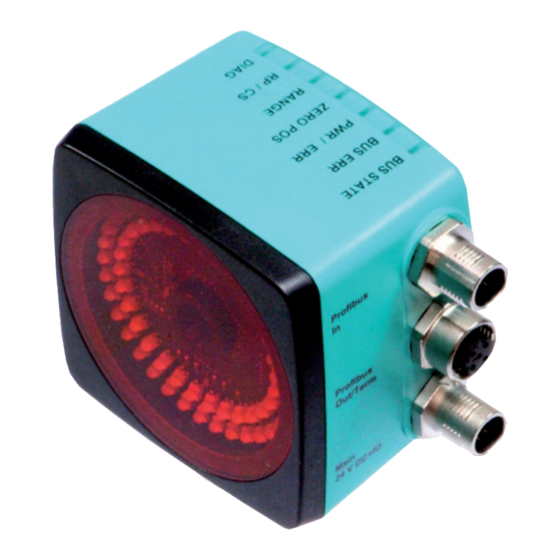
Page 9: Displays And Controls
PHA...-F200-B6-V15B Product Description Displays and Controls The Vision Sensor unit has 7 LED indicators on the top that provide information on the various statuses of the device. Figure 4.2 Indication operating side BUS STATE Yellow LED. Indicates that the sensor communicates with PROFIBUS. BUS ERR Red LED. - Page 10 PHA...-F200-B6-V15B Product Description green/ Color yellow yellow yellow yellow yellow yellow Description Data transfer PROFIBUS flashes PROFIBUS communication error = 1 Hz flash lights up System error lights up Normal operation green X = LED status has no meaning LEDs are mounted around the camera element on the front of the Vision Sensor. The LEDs are used for light, to align the X and Y position, and for the status display.
-
Page 11: Interfaces And Connections
PHA...-F200-B6-V15B Product Description Two operating buttons are mounted on the back of the Vision Sensor. With the operating button 2 "CONFIG" you can configure the fieldbus address using code cards. See chapter 6.3 Figure 4.4 Controls Operating button 2 "CONFIG" Interfaces and Connections The device includes the following connections: Figure 4.5... -
Page 12: Power Supply
If products are used in harsh ambient conditions, appropriate Pepperl+Fuchs accessories can be used to extend the service lives of these products. -
Page 13: Installation
2. Check that all items are present and correct based on your order and the shipping documents. If you have any questions, please contact Pepperl+Fuchs. 3. Keep the original packing material in case you need to store or ship the unit at a later time. -
Page 14: Electrical Connection
PHA...-F200-B6-V15B Installation 93.8 21.75 M6 x 9 (4x) The surface must be level in order to prevent the housing from becoming distorted when the fittings are tightened. We advise securing the screws with spring disks in order to prevent the sensor becoming misaligned. Following installation of the sensor, ensure that there is still sufficient space to connect the connecting cable to the sensor. - Page 15 Main Figure 5.2 Color Assignment Pepperl+Fuchs female cordsets are manufactured in accordance with EN 60947- 5-2. When using a type V19-... (see chapter 4.5.2) female cordset with an open cable end on the Main connection, the following color assignment applies:...
-
Page 16: Profibus Connection
PHA...-F200-B6-V15B Installation Direct the protective grounding connections to a collective point in a star ■ configuration. The cross-section of the cables used for grounding should be as large as ■ possible. Caution! Damage to the device Connecting an alternating current or excessive supply voltage can damage the device or cause the device to malfunction. -
Page 17: Commissioning
PHA...-F200-B6-V15B Commissioning Commissioning Sensor Functionality The PHA...-F200* Vision Sensor detects circular holes in the rack structure and determines their position deviation from the target position. The Vision Sensor operates in two dimensions — X and Y, X being the horizontal direction and Y the vertical direction. - Page 18 PHA...-F200-B6-V15B Commissioning Capture range The capture range is the area in the camera's line of vision, within which the Vision Sensor can detect a hole. The hole diameter should be 10–15 % of the capture range width. Tolerance range The sensor provides the -X, +X, -Y, +Y deviation as an LED display. The target position is located within a rectangular tolerance range.
-
Page 19: Operating Modes
PHA...-F200-B6-V15B Commissioning Operating Modes The sensor has two operating modes: Setup ■ Automatic ■ In setup mode, the sensor parameterization can be changed and diagnostic functions called up. The sensor is always in automatic mode once the operating voltage has been applied. External Parameterization of the Fieldbus using Code Cards During the external configuration of the fieldbus address, the read head optically senses special code cards and then sets the respective fieldbus address. -
Page 20: Operation
PHA...-F200-B6-V15B Operation Operation Communication via PROFIBUS 7.1.1 General information on PROFIBUS DP The PROFIBUS DP is a standardized, open fieldbus, which enables data exchange between PLCs, PCs, operating and observation devices, and also sensors and actuators. For more detailed information on the PROFIBUS DP, refer to the PROFIBUS standard EN 50170 and to the current literature on the subject (e.g. -
Page 21: Profibus Modules
PHA...-F200-B6-V15B Operation 7.1.5 PROFIBUS Modules The PROFIBUS address for the read head can be modified in a nonvolatile manner via the "Change Station Address" (Set_Slave_Add) PROFIBUS function when switching on in a point-to-point connection. The default address for the read head is 3. 1 word = 16-bit value 1 byte = 8-bit value The following modules enable read head data to be called up via PROFIBUS. - Page 22 PHA...-F200-B6-V15B Operation Deviation Y coordinate Module Module No. Size Type Content 2 words Input data 32 Bit Y data consistent MSB first Two's complement -100 000 to 100 000 m Response Content Word 1 Word 2 Bit No. Y data X data YD16 YD00...
- Page 23 PHA...-F200-B6-V15B Operation Status Module Module No. Size Type Content 1 Word Input data 8 Bit status consistent MSB first Response Content Word 1 Bit No. Status ST00 ST01 ST02 ST03 ST04 ST05 ST06 ST07 Radius Module Module No. Size Type Content 1 Word Input data...
- Page 24 PHA...-F200-B6-V15B Operation Counter Module Module No. Size Type Content 1 Word Input data 8 Bit counter consistent MSB first 0 to 255 Response Content Word 1 Bit No. Counter CNT00 CNT01 CNT02 CNT03 CNT04 CNT05 CNT06 CNT07...
- Page 25 PHA...-F200-B6-V15B Operation Duration LED flash Module Module No. Size Type Content 1 Word Input data 16 Bit flashtime consistent MSB first 0 to 255 s Response Content Word 1 Bit No. Flashtime FT00 FT01 FT02 FT03 FT04 FT05 FT06 FT07 FT08 FT09 FT10...
-
Page 26: Global Primary Data
PHA...-F200-B6-V15B Operation 7.1.6 Global Primary Data With the global primary data you can parameterize the read head via PROFIBUS. The global primary data is always transferred completely to the read head. Primary data Designation Function Type min. max. default Hole Diameter Diameter of the hole to be Uint8 1 mm... -
Page 27: Maintenance And Repair
PHA...-F200-B6-V15B Maintenance and repair Maintenance and repair Maintenance The cable is maintenance-free. To get the best possible performance out of your device, keep the optical unit on the device clean and clean it when necessary. Observe the following instructions when cleaning: Do not touch the optical unit with your fingers. -
Page 28: Troubleshooting
PHA...-F200-B6-V15B Troubleshooting Troubleshooting What to Do in the Event of an Error Before you have the device repaired, take the following actions: Test the equipment according to the checklist below. ■ Contact our Service Center in order to localize the problem. ■... - Page 29 PHA...-F200-B6-V15B Troubleshooting...
- Page 30 Twinsburg, Ohio 44087 · USA Tel. +1 330 4253555 E-mail: sales@us.pepperl-fuchs.com Asia Pacific Headquarters Pepperl+Fuchs Pte Ltd. Company Registration No. 199003130E Singapore 139942 Tel. +65 67799091 E-mail: sales@sg.pepperl-fuchs.com www.pepperl-fuchs.com Subject to modifications Copyright PEPPERL+FUCHS • Printed in Germany TDOCT3036A_ENG 06/2013...
Need help?
Do you have a question about the PHA-F200-B6-V15B Series and is the answer not in the manual?
Questions and answers