
Subscribe to Our Youtube Channel
Related Manuals for Pepperl+Fuchs PHA Series


Summary of Contents for Pepperl+Fuchs PHA Series
- Page 1 FACTORY AUTOMATION MANUAL PHA...-F200*-R2* Vision sensor for precision positioning...
- Page 2 PHA...-F200*-R2* With regard to the supply of products, the current issue of the following document is applicable: The General Terms of Delivery for Products and Services of the Electrical Industry, published by the Central Association of the Electrical Industry (Zentralverband Elektrotechnik und Elektroindustrie (ZVEI) e.V.) in its most recent version as well as the supplementary clause: "Expanded reservation of proprietorship"...
-
Page 3: Table Of Contents
PHA...-F200*-R2* Contents 1 Introduction................. 4 2 Declaration of conformity ..........5 3 Safety................... 6 Symbols relevant to safety ................6 Intended Use ....................6 General safety instructions ................6 4 Product Description ............7 Use and Applications ..................7 Displays and Controls ...................8 Interfaces and Connections ................ 10 Scope of Delivery..................12 Accessories .................... -
Page 4: Introduction
PHA...-F200*-R2* Introduction Introduction Congratulations You have chosen a device manufactured by Pepperl+Fuchs. Pepperl+Fuchs develops, produces and distributes electronic sensors and interface modules for the market of automation technology on a worldwide scale. Symbols used The following symbols are used in this manual: Note! This symbol draws your attention to important information. -
Page 5: Declaration Of Conformity
This product was developed and manufactured under observance of the applicable European standards and guidelines. Note! A Declaration of Conformity can be requested from the manufacturer. The product manufacturer, Pepperl+Fuchs GmbH, D-68307 Mannheim, has a certified quality assurance system that conforms to ISO 9001. ISO9001... -
Page 6: Safety
User modification and or repair are dangerous and will void the warranty and exclude the manufacturer from any liability. If serious faults occur, stop using the device. Secure the device against inadvertent operation. In the event of repairs, return the device to your local Pepperl+Fuchs representative or sales office. -
Page 7: Product Description
Product Description Vision Sensor for Rack Fine Positioning — Use and Applications The PHA*...-F200* Vision Sensor for rack fine positioning from Pepperl+Fuchs facilitates fast and simple positioning of stock feeders. The Vision Sensor detects circular holes in the rack structure and determines their position deviation in the X and Y directions relative to the target position. -
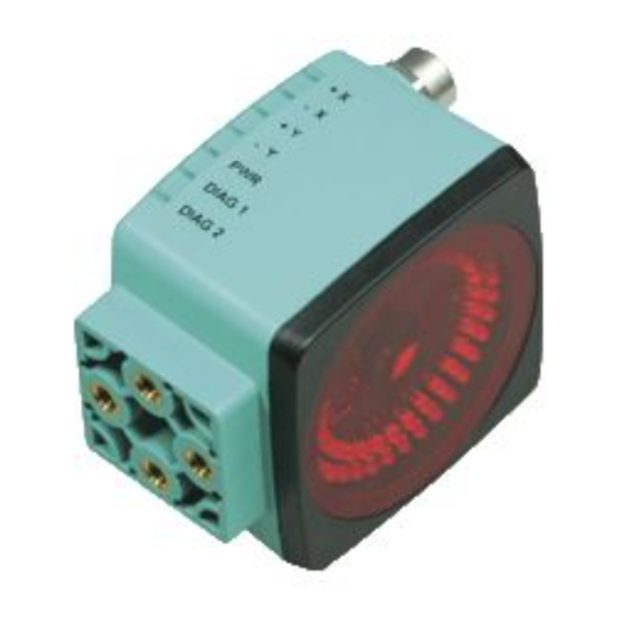
Page 8: Displays And Controls
PHA...-F200*-R2* Product Description Displays and Controls The Vision Sensor unit has 7 LED indicators on the top that provide information on the various statuses of the device. Figure 4.2 Indication operating side +X position LED yellow. Indicates wether the sensor is within the tolerance range. -X position LED yellow. - Page 9 PHA...-F200*-R2* Product Description Figure 4.3 Indication camera side Camera LED infrared illumination -X position LED red. Indicates whether the sensor is within the tolerance range. -Y position LED red. Indicates whether the sensor is within the tolerance range. +X position LED red.
-
Page 10: Interfaces And Connections
PHA...-F200*-R2* Product Description Interfaces and Connections The device includes the following connections: Figure 4.5 Electrical connection LAN (Service interface, M12 socket 4-pin, D-coded) RS232 connection (PLC, M12 socket 5-pin) 24 V DC + IO (Power supply, inputs and outputs, M12 connector 8-pin) Service Interface There is a 4-pin M12 socket on the side of the housing for connecting to a PC. - Page 11 PHA...-F200*-R2* Product Description RS 232 There is a 5-pin M12 socket on the side of the housing for connecting to the PLC. The following diagram shows the pin assignments: Figure 4.7 RS 232 connection layout TX RS 232 RX RS 232 24 VDC + IO (Power Supply, Inputs and Outputs) There is an 8-pin M12 connector on the side of the housing to connect the power supply and the inputs and outputs.
-
Page 12: Scope Of Delivery
PHA...-F200*-R2* Product Description Scope of Delivery PHA* ■ Appropriate mounting hardware, cables, and other information can be found in the Accessories section and at http://www.pepperl-fuchs.com. Accessories Various accessories are available. 4.5.1 Power supply Use the following connection cable to connect the power supply, inputs and outputs to the sensor. -
Page 13: Rs232 Interface
PHA...-F200*-R2* Product Description 4.5.3 RS232 interface The RS232 sensor interface is connected via an M12 connector. Designation Description V15S-G-5M-PUR-ABG Male cordset, M12, 5-pin, PUR cable, shielded cap V15S-G-5M-PUR-ABG-SUBD9 Connection cable, M12 plug, 5-pin, to Sub-D housing, 9-pin Note If you use your Vision Sensor in a refrigeration application at below -20 °C, please ask us for special cables. -
Page 14: Installation
2. Check that all items are present and correct based on your order and the shipping documents. If you have any questions, please contact Pepperl+Fuchs. 3. Keep the original packing material in case you need to store or ship the unit at a later time. - Page 15 PHA...-F200*-R2* Installation 93.8 21.75 M6 x 9 (4x) The surface must be level in order to prevent the housing from becoming distorted when the fittings are tightened. We advise securing the screws with spring disks in order to prevent the sensor becoming misaligned. Following installation of the sensor, ensure that there is still sufficient space to connect the connecting cable to the sensor.
-
Page 16: Connecting The Sensor
PHA...-F200*-R2* Installation Connecting the Sensor Connecting the Supply Voltage To supply voltage to the sensor, proceed as follows: 1. Plug the 8-pin M12 socket into the 24 VDC + IO connector on the side of the housing. see chapter 4.3. 2. -
Page 17: Connection Via A Cbx800 Connector Box
PHA...-F200*-R2* Installation 5.4.1 Connection via a CBX800 Connector Box CBX800 Fieldbus connection PHA...-F200* Power supply Figure 5.2 To connect the Vision Sensor to a fieldbus, we recommend using a CBX800 connector box. The spring terminal strips in the connector box allow simple connection and replacement of the Vision Sensor. -
Page 18: Commissioning
PHA...-F200*-R2* Commissioning Commissioning Sensor Functionality The PHA...-F200* Vision Sensor detects circular holes in the rack structure and determines their position deviation from the target position. The Vision Sensor operates in two dimensions: X and Y. X is the horizontal direction and Y the vertical direction. - Page 19 PHA...-F200*-R2* Commissioning Capture Range The capture range is the area in the camera's line of vision, within which the Vision Sensor can detect a hole. The hole diameter should be 10 % to 15 % of the capture range width. Zero Position and Relative Position The actions to place an object (e.g., a pallet) in storage or remove an object from storage are controlled via the zero position (ZP) and relative position (RP).
- Page 20 PHA...-F200*-R2* Commissioning Zero position (ZP) Figure 6.3 = index hole = pallet = sensor The zero position moves the target position relative to the center point of the detection/capture range Downward if a positive vertical value is entered. ■ To the left if a positive horizontal value is entered. ■...
- Page 21 PHA...-F200*-R2* Commissioning The relative position is activated if a signal is present at input 2. The relative position moves the target position relative to the center point of the detection/capture range Upward if a positive vertical value is entered. ■ To the right if a positive horizontal value is entered.
- Page 22 PHA...-F200*-R2* Commissioning Relative position RP -40 mm C a p t u r e r Vision Configurator a n g e H o l e Zero position Horizontal Vertictal Relative position Horizontal Vertictal Figure 6.6 To move the hole to be detected near to the center of the detection/capture range, adjust the zero position downward by 20 mm.
- Page 23 PHA...-F200*-R2* Commissioning Zero position ZP -20 mm Relative position RP -20 mm Vision Configurator C a p t u r e r a n g e H o l e Zero position Horizontal Vertictal Relative position Horizontal Vertictal Figure 6.8 A distance of 40 mm was achieved overall.
-
Page 24: Operating Modes
PHA...-F200*-R2* Commissioning -X = 1 -X = 1 -X = 0 +X = 0 +X = 1 +X = 1 -Y = 0 -Y = 0 -Y = 0 +Y = 1 +Y = 1 +Y = 1 -X = 1 -X = 0 -X = 1 +X = 0... - Page 25 PHA...-F200*-R2* Commissioning Byte Content Unit 1. digit, X-deviation (ASCII-coded) [m] 2. digit, X-deviation (ASCII-coded) 3. digit, X-deviation (ASCII-coded) 4. digit, X-deviation (ASCII-coded) 5. digit, X-deviation (ASCII-coded) Prefix, Y-deviation (ASCII-coded) 1. digit, Y-deviation (ASCII-coded) [m] 2. digit, Y-deviation (ASCII-coded) 3. digit, Y-deviation (ASCII-coded) 4.
- Page 26 PHA...-F200*-R2* Commissioning Byte Content Unit Internal value (ASCII-coded) Internal value (ASCII-coded) Example of long telegram: <STX>2;+10123;-00034;67;OS;096;000;00045;00040<CR><LF> dx = +10123 m dy = -34 m Sequential number: 67 Measurement: successful Radius: 96% (relative to target value, depending on distance) Exposure time: 45 µs Example of short telegram: <STX>1;+10123;-00034;67;OS<CR><LF>...
-
Page 27: Operation
PHA...-F200*-R2* Operation Operation PHA* Vision Configurator Menu Structure 7.1.1 Connecting the Service Interface Establishing a local Connection To connect the LAN service interface to a PC, proceed as follows: 1. Use a network cable that has an RJ45 network connector on one side and a 4- pin M12 connector on the other. -
Page 28: Structure Of The Application Window
PHA...-F200*-R2* Operation 7.1.2 Structure of the Application Window The application screen opens after you log in. Figure 7.1 The application screen - default user The software is designed to be similar to most Windows applications. Designation Function Title bar Displays the software designation ■... -
Page 29: Menu Bar
PHA...-F200*-R2* Operation Designation Function Results area Displays results from the sensor ■ A varying number of tabs can be displayed depending ■ on which sensor is connected. Typical tabs are: ■ "Image View" — shows images from the sensor that may contain additional information "Result View"... - Page 30 PHA...-F200*-R2* Operation Configuration Window Position Hole Menu Item Application Figure 7.3 Configuration Window General Tab — Common Designation Function Hole Diameter In the "Hole Diameter" field, you can set the hole diameter of the circular holes to be detected. The larger the hole diameter, the easier detection ■...
-
Page 31: Maintenance And Repair
PHA...-F200*-R2* Maintenance and Repair Maintenance and Repair Maintenance The cable is maintenance-free. To get the best possible performance out of your device, keep the optical unit on the device clean and clean it when necessary. Observe the following instructions when cleaning: Do not touch the optical unit with your fingers. -
Page 32: Troubleshooting
PHA...-F200*-R2* Troubleshooting Troubleshooting What to Do in the Event of an Error Before you have the device repaired, take the following actions: Test the equipment according to the checklist below. ■ Contact our Service Center in order to localize the problem. ■... - Page 33 PHA...-F200*-R2* Troubleshooting...
- Page 34 Twinsburg, Ohio 44087 · USA Tel. +1 330 4253555 E-mail: sales@us.pepperl-fuchs.com Asia Pacific Headquarters Pepperl+Fuchs Pte Ltd. Company Registration No. 199003130E Singapore 139942 Tel. +65 67799091 E-mail: sales@sg.pepperl-fuchs.com www.pepperl-fuchs.com Subject to modifications Copyright PEPPERL+FUCHS • Printed in Germany TDOCT2275G_ENG 01/2014...
Need help?
Do you have a question about the PHA Series and is the answer not in the manual?
Questions and answers