Pepperl+Fuchs UC 18GS Series Manual
Configuring ultrasonic sensors with io-link interface
Hide thumbs
Also See for UC 18GS Series:
- Commissioning instruction (2 pages) ,
- Commissioning instruction (2 pages)
Table of Contents
Advertisement
Advertisement
Table of Contents

Related Manuals for Pepperl+Fuchs UC 18GS Series


Summary of Contents for Pepperl+Fuchs UC 18GS Series
- Page 1 UC***-18GS series Configuring Ultrasonic Sensors with IO-Link Interface Manual...
- Page 2 Phone: +49 621 776 - 0 E-mail: info@de.pepperl-fuchs.com North American Headquarters Pepperl+Fuchs Inc. 1600 Enterprise Parkway Twinsburg, Ohio 44087 Phone: +1 330 425-3555 E-mail: sales@us.pepperl-fuchs.com Asia Headquarters Pepperl+Fuchs Pte. Ltd. P+F Building 18 Ayer Rajah Crescent Singapore 139942 Phone: +65 6779-9091 E-mail: sales@sg.pepperl-fuchs.com https://www.pepperl-fuchs.com...
-
Page 3: Table Of Contents
UC***-18GS series Contents Introduction........................ 6 Content of this Document ................6 Target Group, Personnel ................6 Symbols Used ....................6 Intended Use ....................7 General Safety Notes..................7 Declaration of Conformity................8 Product Description ....................9 Use and Application ..................9 Indicators and Operating Elements ............ - Page 4 UC***-18GS series Contents Analysis & Echo Suppression Menu Option ..........31 Observation Menu Option ................38 Service Menu Option ...................42 Information Menu Option ................43 Description of Sensor Parameters.................44 Sensor Information ..................44 Output – Switching Output................44 8.2.1 Output Mode ..................44 8.2.2 Output Logic..................47 8.2.3 Switch Point 1...................47 8.2.4...
- Page 5 UC***-18GS series Contents Sensor Configuration – Synchronization ..........58 Sensor Configuration – Echo Loss and Error Handling ......59 8.6.1 No Echo................... 59 8.6.2 Output Behavior if an Error Occurs ..........60 8.6.3 Error Replacement Value – Current/Voltage........60 Sensor Configuration – Local Controls ............. 61 8.7.1 Local Controls..................
-
Page 6: Introduction
UC***-18GS series Introduction Introduction Content of this Document This document contains information required to use the product in the relevant phases of the product life cycle. This may include information on the following: • Product identification • Delivery, transport, and storage •... -
Page 7: Symbols Used
UC***-18GS series Introduction Symbols Used This document contains symbols for the identification of warning messages and of informative messages. Warning Messages You will find warning messages, whenever dangers may arise from your actions. It is mandatory that you observe these warning messages for your personal safety and in order to avoid prop- erty damage. -
Page 8: General Safety Notes
If serious faults occur, stop using the device. Secure the device against inadvertent operation. In the event of repairs, return the device to your local Pepperl+Fuchs representative or sales office. -
Page 9: Product Description
UC***-18GS series Product Description Product Description Use and Application The UC***-18GS series ultrasonic sensors use ultrasonic pulses to detect objects. The sensor emits ultrasound, which is reflected by the object and received again by the sensor. The mea- sured sound propagation time is used to determine the distance to the object (pulse-echo prin- ciple). - Page 10 If you use the "IO-Link Offline Parameterization Tool" software package, have active internet access, and have connected your device via the Pepperl+Fuchs IO-Link USB master, the PACTware will automatically find the right IODD online.
-
Page 11: Indicators And Operating Elements
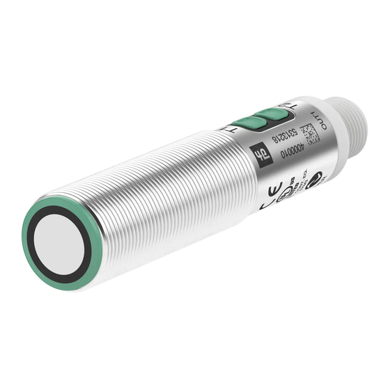
UC***-18GS series Product Description Indicators and Operating Elements Figure 2.1 1. Yellow/green/red LED 2. Programming button T1 3. Programming button T2 4. Sonically-active area LED display for sensors with switching output Green LED Yellow LED Red LED In normal operation Error-free operation Switch state Fault (e.g., compressed air) - Page 12 UC***-18GS series Product Description LED display for sensors with analog output Green LED Yellow LED Red LED In normal operation Error-free operation Output state Fault (e.g., compressed air) Retains previous state (factory default setting, can be changed via IO-Link) Standby (high level for > 1 s at Flashing Retains previous state synchronization input)
-
Page 13: Accessories
UC***-18GS series Product Description Accessories Various accessories are available. 2.3.1 Accessories for Mounting and Connection Several components are available for mounting and connecting UC***-18GS series sensors. You will find details online at www.pepperl-fuchs.com on the product page for the relevant sensor or on the relevant datasheet. -
Page 14: Installation
Check the package contents against your order and the shipping documents to ensure that all items are present and correct. Should you have any questions, direct them to Pepperl+Fuchs. Retain the original packaging in case the device is to be stored or shipped again at a later date. -
Page 15: Connection
UC***-18GS series Installation Connection Note A three-pin adapter or triple-strand connection cable must be used when connecting the sensor to an IO-Link Class B master port. If the synchronization option is unused, connect the synchronization input to ground (0 V) during operation without IO-Link. -
Page 16: Commissioning Without Io-Link
UC***-18GS series Commissioning without IO-Link Commissioning without IO-Link Switch on the supply voltage. The operating indicator on the sensor lights up green. The sensor will now function using the preset parameters. Note It is only possible to change configuration by programming with the programming button or by configuring via IO-Link! -
Page 17: Sensor Programming Via The Programming Button
UC***-18GS series Sensor Programming via the Programming Button Sensor Programming via the Programming Button Basic information about programming In terms of factory settings, the sensor can only be programmed during the first 5 minutes after switching on. This time is extended during the actual programming process. The option of pro- gramming the sensor is revoked if no programming activities take place for 5 minutes. - Page 18 UC***-18GS series Sensor Programming via the Programming Button Figure 5.1 Programming Switch Point 1 / Near Limit (SP1) If the object is detected correctly during the programming process, the yellow LED flashes slowly. If no object is detected, the yellow LED flashes at a higher frequency. A flashing red LED during or when completing the programming process indicates unreliable object detection.
-
Page 19: Programming Sensor Operating Modes For Switching Output
UC***-18GS series Sensor Programming via the Programming Button Programming Sensor Operating Modes for Switching Output The sensor features a 3-stage process for programming the sensor operating modes. In this programming routine you can program as follows: • A) Output mode •... -
Page 20: Programming The Sensor Operating Modes For Analog Output
UC***-18GS series Sensor Programming via the Programming Button The red LED is now flashing. The number of flashing pulses indicates the currently pro- grammed sound beam width: 1x: narrow 2x: medium 3x: wide The sound beam width is generally set only once for the sensor. Briefly press the programming button to navigate through the sound beam widths in succession. - Page 21 UC***-18GS series Sensor Programming via the Programming Button The yellow LED is now flashing. The number of flashing pulses indicates the currently pro- grammed output type: 1x: current output 2x: voltage output Briefly press the programming button to navigate through the output types in succession. Select the required output type.
-
Page 22: Commissioning Using Pactware And Dtm
UC***-18GS series Commissioning Using PACTware and DTM Commissioning Using PACTware and DTM There is a DTM available to download to help you fully configure the sensor easily via IO-Link. Visit www.pepperl-fuchs.com and access the product page for the relevant UC***-18GS series sensor. - Page 23 UC***-18GS series Commissioning Using PACTware and DTM Click Search new device. The IO-Link USB master will be identified by the PACTware DC if it is connected to the PC. Figure 6.2 In the Project, click IO-Link USB Master... The PACTware DC automatically establishes the connection to the sensor if the ultrasonic sensor is connected to the IO-Link USB master.
-
Page 24: Commissioning Using Irda Infrared Interface
Refer to the datasheet for the UC-PROG-IR-USB interface cable and read the description regarding correct orientation of the sensor to the interface cable. The "Pepperl+Fuchs PACTware Connection Wizard" is available to help you launch and con- nect the sensor easily. The wizard takes you through all the necessary steps for opening a PACTware project. - Page 25 UC***-18GS series Commissioning Using PACTware and DTM Setting Up Sensor Communication Using PACTware DC Launch PACTware DC by double-clicking the PACTware DC icon. Figure 6.5 Click Search new device. If the UC-PROG-IR-USB interface cable is connected to the PC, it will be detected by the PACTware DC.
- Page 26 "Pepperl + Fuchs PACTware Connection Wiz- ard." This wizard assumes all necessary steps in opening a PACTware project. Double-click the "Pepperl+Fuchs PACTware Connection Wizard" icon. Loads PACTware and the associated DTM and the connection to the sensor is automatically...
-
Page 27: Configuration And Analysis With Dtm Via Io-Link
UC***-18GS series Configuration and Analysis with DTM via IO-Link Configuration and Analysis with DTM via IO-Link Overview The sensor parameters are different for each device. These parameters are clearly set out in the DTM (Device Type Manager), with guidance being provided in the form of graphics for some of the parameters. -
Page 28: Sensor Information Menu Option
UC***-18GS series Configuration and Analysis with DTM via IO-Link Sensor Information Menu Option Preprogrammed manufacturer and device information is displayed in the Sensor information Figure 7.2 • menu option, and the number of operating hours. These are read-only fields. • You can input application-specific tags to identify and mark your sensor in the system environment. -
Page 29: Sensor Configuration Menu Option
UC***-18GS series Configuration and Analysis with DTM via IO-Link Sensor Configuration Menu Option Overview of the Sensor Configuration Menu Option Figure 7.4 The Sensor configuration menu option consists of 4 tabs • Evaluation (with reduced and advanced view) • Synchronization •... - Page 30 UC***-18GS series Configuration and Analysis with DTM via IO-Link Synchronization Tab Figure 7.6 In the Synchronization tab, you can set the required synchronization mode if you want to sup- press cross-talk when operating several UC***-F77-...-IO-.. sensors. Details of the individual synchronization modes can be found in the chapter "Synchronizing Multiple Sensors."...
-
Page 31: Analysis & Echo Suppression Menu Option
UC***-18GS series Configuration and Analysis with DTM via IO-Link Analysis & Echo Suppression Menu Option Figure 7.9 In some applications, machine parts or support bars within a tank obstruct the sensing area, preventing proper distance or level measurement. Using the Analysis & Echo Suppression menu option, you can visualize and analyze all echoes received by the ultrasonic sensor from one or a series of measurements, as well as suppress the disruptive objects in the sensing area. - Page 32 UC***-18GS series Configuration and Analysis with DTM via IO-Link Menu Description Figure 7.10 No. Name Description Echo sampling In the "Echo sampling" area, you can choose whether to record a single value, 50 values or continuous data. Using the continuous display also provides you with an alignment aid.
- Page 33 UC***-18GS series Configuration and Analysis with DTM via IO-Link No. Name Description Load file You can load previously-saved echo samples to the DTM by pressing the "Load file" button, allowing you to assess or evaluate the samples. Note: You can only load a saved file if disconnected from the sen- sor.
- Page 34 UC***-18GS series Configuration and Analysis with DTM via IO-Link Details about sampled echoes Using an echo sample with manual echo suppression as an example, the following sets out the graphic elements of information in the display area. Figure 7.11 No. Name Description Suppression area A rectangle indicates the specified suppression area.
- Page 35 UC***-18GS series Configuration and Analysis with DTM via IO-Link No. Name Description Details of the Clicking on a column from the echo sample displays the following selected echo detailed information in the "Details of the selected echo" area: • Echo number: The echo number is a consecutive number which numbers the echoes shown in the graphic from left to right.
- Page 36 UC***-18GS series Configuration and Analysis with DTM via IO-Link Application Information for Echo Suppression In order to be able to suppress echoes, you first have to set the "Echo suppression" parameter to "enabled," provided that the parameter is not already set accordingly in the connected sen- sor.
- Page 37 UC***-18GS series Configuration and Analysis with DTM via IO-Link Example In terms of the following echo sample, the echo labeled with the red arrow should be sup- pressed. The echo labeled with the green arrow echo comes from the object that is to be detected (e.g., the level surface).
- Page 38 UC***-18GS series Configuration and Analysis with DTM via IO-Link The graphic with set suppression area for an interior application is as follows: Figure 7.13 Note The boundaries of suppression areas can also be adjusted directly within the graphic by left- clicking and dragging with the mouse.
-
Page 39: Observation Menu Option
UC***-18GS series Configuration and Analysis with DTM via IO-Link Observation Menu Option Figure 7.14 You can use the Observation menu option to track and record data from the ultrasonic sensor over time, and the corresponding behavior of the switching and analog outputs. You can choose from the "Visual observation"... - Page 40 UC***-18GS series Configuration and Analysis with DTM via IO-Link Menu Description Figure 7.15 No. Name Description Follow mode on / off If follow mode is "On," data is displayed in accordance with the current rescale setting of the x-axis. The measured value is visible in the display.
- Page 41 UC***-18GS series Configuration and Analysis with DTM via IO-Link No. Name Description Output By clicking on the check box, you can enable or disable display of the output status (0/1) in the display area in the form of a green line.
- Page 42 UC***-18GS series Configuration and Analysis with DTM via IO-Link Data Logging Setting Pressing the "Settings for data logging" button opens the menu displayed below. Figure 7.16 You can use the "Name of log file" field to set the file path and file names for logging data. You can select "Data logging mode"...
- Page 43 UC***-18GS series Configuration and Analysis with DTM via IO-Link • Value outside the set limits Data is recorded if specified, absolute limit values are exceeded. The distance value in mm and the value at the sensor analog output (if physically present on the sensor) are available as reference values.
-
Page 44: Service Menu Option
UC***-18GS series Configuration and Analysis with DTM via IO-Link Service Menu Option Figure 7.17 You can use the Service menu option to set the following service functions. • Reset to factory defaults: activating the switch resets the sensor to settings as deliv- ered. -
Page 45: Description Of Sensor Parameters
UC***-18GS series Description of Sensor Parameters Description of Sensor Parameters Sensor Information Application-specific tag Parameter name Access Value range Application-specific tag Read/write 32 alphanumeric characters Table 8.1 The user can use this parameter to tag the sensor, e.g., "Tank 2 fill level" or to tag the sensor in the plant design. - Page 46 UC***-18GS series Description of Sensor Parameters Switch point mode If the mode is set to "Switch point mode," the output status changes at the set switch point 1. The direction of motion or fill level of the object, to or from the sensor, and any configured switch point 2 are not relevant.
- Page 47 UC***-18GS series Description of Sensor Parameters Hysteresis Mode In "Hysteresis mode" output mode, the status of the switching output changes if an object is approaching switch point 1. The status will change back to the previous value when the object passes switch point 2.
-
Page 48: Output Logic
The DTM also accepts values between <Beginning of sensing range> and <Beginning of adjustment range> as well as values above <End of adjustment range> up to a certain limit. Values in these ranges are outside of the adjustment range specified by Pepperl+Fuchs; use them at your own risk. -
Page 49: Retroreflective Mode Offset
The DTM also accepts values between <Beginning of sensing range> and <Beginning of adjustment range> as well as values above <End of adjustment range> up to a certain limit. Values in these ranges are outside of the adjustment range specified by Pepperl+Fuchs; use them at your own risk. -
Page 50: Switching Hysteresis
UC***-18GS series Description of Sensor Parameters Note An offset value of at least 10 % of the reflector distance is typically recommended to prevent impact of temperature fluctuations, in outdoor applications too. 8.2.6 Switching Hysteresis Note The "Switching hysteresis" parameter is not relevant if output mode is set to "Hysteresis mode" and is hidden in the DTM. -
Page 51: Switch-Off Delay
UC***-18GS series Description of Sensor Parameters 8.2.8 Switch-Off Delay Note This parameter influences the response time of the sensor. Parameter name Access Value range Switch-off delay Read/write 0 ... 60000 [ms] Table 8.9 You can use the "Switch-off delay" parameter to delay the switching output being switched off. This delay can be helpful if very fast events need to be reliably reported by programmable logic controllers with slower cycle time. -
Page 52: Near Limit
The DTM also accepts values between <Beginning of sensing range> and <Beginning of adjustment range> as well as values above <End of adjustment range> up to a certain limit. Values in these ranges are outside of the adjustment range specified by Pepperl+Fuchs; use them at your own risk. -
Page 53: Upper Output Value
UC***-18GS series Description of Sensor Parameters 8.3.6 Upper Output Value Note The DTM will display just the appropriate upper output value depending on the set output type for the analog output (current or voltage). Parameter name Access Value range Upper output value – Current Read/write 0 ... -
Page 54: Echo Evaluation
UC***-18GS series Description of Sensor Parameters Medium beam width Parameter name Access Value range Medium beam width Read/write 10 ... 100 [% in increments of 10 %] Table 8.18 This enables you to further adjust the width of this sound beam in a range of 10 ... 100 % according to the previous selection of the medium beam width (via parameter or programming button). -
Page 55: Evaluation Method
UC***-18GS series Description of Sensor Parameters 8.4.3 Evaluation Method Note This parameter is visible in the DTM advanced view. Parameter name Access Value range Evaluation method Read/write • Average value • Low pass • None Table 8.21 The "Evaluation method" parameter allows you to specify the extent to which values of previous measurements are included in the evaluation of the current measurement. -
Page 56: Averages & Skip Count
UC***-18GS series Description of Sensor Parameters 8.4.4 Averages & Skip Count Note This parameter is only relevant and visible in the DTM if the "Evaluation method" is set to "Average value." Parameter name Access Value range Averages & skip count Read/write •... -
Page 57: Allowed Deviation To The Former Measurement
UC***-18GS series Description of Sensor Parameters This means that the less the "Weighting of former measurement" value, the closer the sensor's output follows the real distance. 8.4.6 Allowed Deviation to the Former Measurement Note This parameter is only relevant and visible in the DTM if the "Evaluation method" parameter is set to "Low pass."... -
Page 58: Temperature Compensation
UC***-18GS series Description of Sensor Parameters 8.4.8 Temperature Compensation Note This parameter is visible in the DTM advanced view. Parameter name Access Value range Temperature compensation Read/write • Inactive • Active (factory setting) • Active with power-on-drift compensation Table 8.26 The speed of sound and subsequently an ultrasonic sensor's accuracy is affected by changes in ambient temperature. -
Page 59: Operating Temperature
UC***-18GS series Description of Sensor Parameters 8.4.9 Operating Temperature Note This parameter is visible in the DTM advanced view. Parameter name Access Value range Operating temperature Read/write -40 ... 100 [°C] Table 8.27 With disabled temperature compensation (see "Temperature compensation" parameter), the operating temperature specified here is used to calculate the object distance from the mea- sured sound propagation time. -
Page 60: Sensor Cycle Time
UC***-18GS series Description of Sensor Parameters 8.4.12 Sensor Cycle Time Note This parameter is only visible in the DTM advanced view. Parameter name Access Value range Sensor cycle time Read/write <min. cycle time> ... 60000 [ms] Table 8.30 You can use the "Sensor cycle time" parameter to specify the length of a measuring cycle. The minimum allowable cycle time depends on the range of the respective sensor and is set at the factory. -
Page 61: Sensor Configuration - Synchronization
UC***-18GS series Description of Sensor Parameters Sensor Configuration – Synchronization Note In addition to setting the "Synchronization mode" parameter, further measures are necessary for synchronization to be successful. This could include connecting the devices to each other accordingly. The commissioning instructions for the respective sensor provide details on this. Synchronization Mode Parameter name Access... -
Page 62: Sensor Configuration - Echo Loss And Error Handling
UC***-18GS series Description of Sensor Parameters Sensor Configuration – Echo Loss and Error Handling 8.6.1 No Echo Parameter name Access Value range No echo Read/write • No error • Error Table 8.33 You can use this parameter to confirm whether "Sensor receives no echo" should be classified as an error or not. -
Page 63: Error Replacement Value - Current/Voltage
UC***-18GS series Description of Sensor Parameters Parameter value Meaning Open This setting is only available for switching outputs. It sets the output status to "Open" in the event of an error. Replacement value This setting is only available for analog outputs. It specifies that in the event of an error, a certain output value should be output at the analog output. -
Page 64: Local Controls Status
UC***-18GS series Description of Sensor Parameters 8.7.2 Local Controls Status Parameter name Access Value range Local controls status Read only • Button not pressed • Button pressed Table 8.37 You can use this parameter to check that the programming button on the sensor is working properly. -
Page 65: Synchronizing Multiple Sensors
UC***-18GS series Synchronizing Multiple Sensors Synchronizing Multiple Sensors The sensor is fitted with a synchronization connector that suppresses mutual interference from external ultrasonic signals. The following 3 types of synchronization can be set: • Automatic multiplex mode • Automatic common mode •... -
Page 66: Maintenance And Repair
UC***-18GS series Maintenance and Repair Maintenance and Repair 10.1 Maintenance Work The sensor itself is maintenance-free. For this reason, it is not necessary to carry out regular adjustments or maintenance work on the sensor itself. However, check that the sensor and connector are tight within the scope of routine mainte- nance intervals. -
Page 67: Troubleshooting
If none of the information specified in the checklist solves the problem, in the event of queries contact Pepperl+Fuchs via your sales office. Have details of the model number and firmware version of the sensor ready if possible. - Page 68 Pepperl+Fuchs Quality Download our latest policy here: www.pepperl-fuchs.com/quality www.pepperl-fuchs.com © Pepperl+Fuchs · Subject to modifications Printed in Germany / DOCT-6942...
Need help?
Do you have a question about the UC 18GS Series and is the answer not in the manual?
Questions and answers