Table of Contents
Advertisement
Quick Links
Advertisement
Table of Contents

Subscribe to Our Youtube Channel
Related Manuals for Pepperl+Fuchs VIM3 IO Series


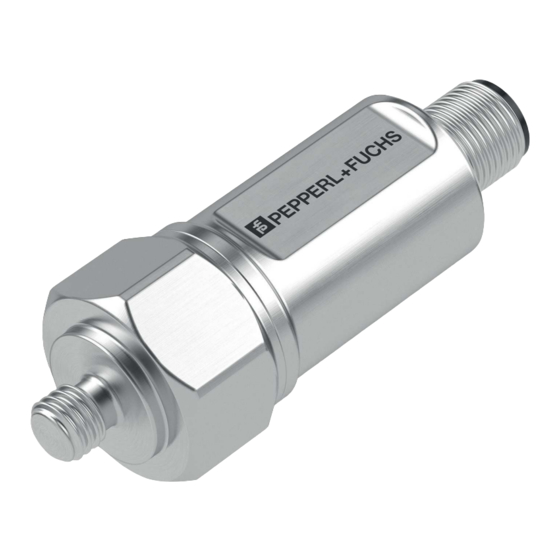
Summary of Contents for Pepperl+Fuchs VIM3 IO Series
- Page 1 VIM3*-IO-* Vibration Sensors Manual...
- Page 2 Phone: +49 621 776 - 0 E-mail: info@de.pepperl-fuchs.com North American Headquarters Pepperl+Fuchs Inc. 1600 Enterprise Parkway Twinsburg, Ohio 44087 Phone: +1 330 425-3555 E-mail: sales@us.pepperl-fuchs.com Asia Headquarters Pepperl+Fuchs Pte. Ltd. P+F Building 18 Ayer Rajah Crescent Singapore 139942 Phone: +65 6779-9091 E-mail: sales@sg.pepperl-fuchs.com https://www.pepperl-fuchs.com...
-
Page 3: Table Of Contents
VIM3*-IO-* Vibration Sensors Contents Introduction........................ 4 Content of this Document ................4 Target Group, Personnel ................4 Symbols Used ....................5 Intended Use ....................5 General Safety Instructions ................6 Product Description ....................7 Use and Application ..................7 Vibration Monitoring..................8 2.2.1 Vibration Velocity Operating Range .................. -
Page 4: Introduction
VIM3*-IO-* Vibration Sensors Introduction Introduction Content of this Document This document contains information that you need in order to use your product throughout the applicable stages of the product life cycle. These can include the following: • Product identification • Delivery, transport, and storage •... -
Page 5: Symbols Used
VIM3*-IO-* Vibration Sensors Introduction Symbols Used This document contains symbols for the identification of warning messages and of informative messages. Warning Messages You will find warning messages, whenever dangers may arise from your actions. It is mandatory that you observe these warning messages for your personal safety and in order to avoid prop- erty damage. -
Page 6: General Safety Instructions
In the event of any serious errors, stop using the device. Secure the device against unintended operation. To have the device repaired, return it to your local Pepperl+Fuchs representative or your sales center. Note Disposal Electronic waste is dangerous. -
Page 7: Product Description
If the "IO-Link Offline Parameterization Tool" software package is used, there is active internet access, and the device is connected via the Pepperl+Fuchs IO-Link USB master, the IODD can be directly integrated into the IO-Link Offline Parameterization Tool via the "IODD DTM Config- urator."... -
Page 8: Vibration Monitoring
VIM3*-IO-* Vibration Sensors Product Description Online Parameterization When commissioning machines and plants, master and IO-Link devices must be integrated into the appropriate control environment. Depending on the components used, different soft- ware is required. The devices can be configured and parameterized using an IO-Link configuration tool. During operation, the parameters for the IO-Link devices can be checked and status and diagnostic data can be read and monitored. - Page 9 VIM3*-IO-* Vibration Sensors Product Description The following figure depicting the vibration monitoring shows the operating range, which is lim- ited by the maximum measurable vibration velocity in mm/s depending on the frequency. The area above the curve shows the operating range that cannot be measured when recording the vibration velocity, because the frequency is too high.
-
Page 10: Frequency Response
VIM3*-IO-* Vibration Sensors Product Description 2.2.2 Frequency Response The typical frequency response of vibration monitoring for two frequency ranges is depicted below. Frequency Response: 10 Hz to 1000 Hz The cut-off frequencies are 10 Hz and 1000 Hz with -3 dB damping. Figure 2.2 Frequency in Hz Gain in dB... -
Page 11: Accessories
VIM3*-IO-* Vibration Sensors Product Description Accessories Note Various accessories are available for the VIM3* vibration sensors. These are available online at www.pepperl-fuchs.com, on the product page for the relevant VIM3* vibration sensor. Available Accessories Accessories Cordset for plug versions Electrical installation for plug versions EMC adapter For insulating the sensor from the mounting point to protect against sources of EMC interference. -
Page 12: Installation
VIM3*-IO-* Vibration Sensors Installation Installation Instructions for Mechanical and Electrical Installation Note Further installation-relevant information on technical data, mechanical data, and available connection lines for the relevant vibration sensor types can be found in the corresponding datasheet. Always observe the following instructions to ensure safe operation of the vibration sensor: Warning! Work must be performed by trained and qualified personnel only! Commissioning and operation of this electrical device must be performed by trained and quali-... -
Page 13: Mounting
VIM3*-IO-* Vibration Sensors Installation Mounting Prerequisites Mounting the vibration sensor on the mounting surface: • The mounting surface must be clean and flat, i.e., free of paint, rust, etc. • The measuring head surface of the vibration sensor must lie flat on the mounting surface. •... -
Page 14: Cybersecurity And Decommissioning Information
Ensure that the IO-Link device communicates with the remote station via a point-to-point connection. The product features a proprietary Pepperl+Fuchs service interface that uses the existing con- nection lines. This interface is used exclusively for initially storing and updating the firmware during production. -
Page 15: Commissioning With Io-Link On A Control Panel (Online Parameterization)
VIM3*-IO-* Vibration Sensors Commissioning with IO-Link on a Control Panel (Online Parameterization) Commissioning with IO-Link on a Control Panel (Online Parameterization) Note The device description file (IODD) required for integration in an IO-Link system and for parameterization and diagnosis is available online. Visit www.pepperl-fuchs.com and navigate to the relevant product page for the VIM3*-IO-* vibration sensor. -
Page 16: Commissioning With Io-Link Via Ftd Framework Program (Offline Parameterization)
If the "IO-Link Offline Parameterization Tool" software package is used, there is active internet access, and the device is connected via the Pepperl+Fuchs IO-Link USB master, the IODD can be directly integrated into the IO-Link Offline Parameterization Tool via the "IODD DTM Config- urator."... -
Page 17: Process Data Structure
VIM3*-IO-* Vibration Sensors Process Data Structure Process Data Structure Four different measured variables are transmitted as process data by the VIM3*-IO-* vibration sensor. These are each transmitted as a Measurement Data Channel (MDC) 1 ... 4. These are Velocity RMS, Vibration Acceleration RMS, Vibration Acceleration Peak, and Temperature. The figure below illustrates the process data structure: Process data SSC1.1... -
Page 18: Parameterizing A Switching Signal (Sscx)
VIM3*-IO-* Vibration Sensors Process Data Structure Parameterizing a Switching Signal (SSCx) Two independent switching signals (SSC) can be parameterized for each measured variable. The principle for parameterization is the same for each measured variable (SSC). The figure below illustrates the relationships: Process data Process data Parameter for setting SSC... -
Page 19: Parameterizing A Plant Maintenance Cycle
VIM3*-IO-* Vibration Sensors Process Data Structure Parameterizing a Plant Maintenance Cycle A plant maintenance cycle can be parameterized by defining the monitored threshold values that correspond to the measured variables of the cyclic process data. The threshold values are independent of the SSCx switch points from the process data. For example, a plant mainte- nance cycle can be defined by exceeding the vRMS vibration velocity thresholds. -
Page 20: Troubleshooting
In case of a fault, use the following checklist to determine whether a fault with the vibration monitoring can be remedied. If none of the information provided in the checklist solves the problem, contact Pepperl+Fuchs via your sales office with any queries. Have details of the model number and firmware version of the sensor ready if possible. -
Page 21: Repair And Servicing
VIM3*-IO-* Vibration Sensors Repair and Servicing Repair and Servicing The device must not be repaired, changed, or manipulated. In case of failure, always replace the device with an original device. - Page 22 Pepperl+Fuchs Quality Download our latest policy here: www.pepperl-fuchs.com/quality www.pepperl-fuchs.com © Pepperl+Fuchs · Subject to modifications / DOCT-8389...
Need help?
Do you have a question about the VIM3 IO Series and is the answer not in the manual?
Questions and answers