Table of Contents
Advertisement
Quick Links
Download this manual
See also:
User Manual
Advertisement
Table of Contents

Related Manuals for Aaeon EMB-BT1


Summary of Contents for Aaeon EMB-BT1
- Page 1 EMB-BT1...
- Page 2 E8771 First Edition January 2014 Copyright Notice This document is copyrighted, 2014. All rights are reserved. The original manufacturer reserves the right to make improvements to the products described in this manual at any time without notice. No part of this manual may be reproduced, copied, translated, or transmitted in any form or by any means without the prior written permission of the original manufacturer.
-
Page 3: Table Of Contents
Contents Chapter 1 Product overview Package contents ................. 1-1 Features ..................1-1 1.3 Specifications ................1-2 Chapter 2 Motherboard information Before you proceed ..............2-1 Motherboard layout ..............2-2 Screw size ..................2-4 2.3.1 Component side .............. 2-4 2.3.2 Solder side ..............2-5 Central Processing Unit (CPU) ........... - Page 4 3.3.8 Miscellaneous Configuration ..........3-11 3.3.9 System Component ............3-12 3.3.10 PCI Subsystem Settings ..........3-12 3.3.11 Dynamic Digital IO ............3-15 3.3.12 Trusted Computing ............3-15 3.3.13 USB Configuration ............3-15 3.3.13 Platform Trust Technology..........3-16 3.3.14 Security Configuration ........... 3-17 Chipset menu ................3-17 3.4.1 North Bridge ..............
-
Page 5: Chapter 1 Product Overview
Chapter 1 Product overview Package contents Check your industrial motherboard package for the following items. 1 x Industrial Motherboard 1 x SATA Cable 1 x I/O Shield 1 x Support CD If any of the above items is damaged or missing, contact your distributor or sales representative immediately. -
Page 6: Specifications
6.7 in. x 6.7 in. (17.0 cm x 17.0 cm) Gross weight 1.1 lb (0.5 Kg) Operating F~140 F (0 C~60 temperature Storage temperature F~185 F (-40 C~85 Operating humidity 0%~90% relative humidity, non-condensing Power compliance Compliant with Eup/ErP Certificate CE/FCC (continued on the next page) EMB-BT1... - Page 7 DISPLAY Chipset Intel Graphics Media Accelerator ® Resolution Up to 1920x1200@60Hz for VGA Up to 1920x1200@60Hz for HDMI Up to 1920x1080@60Hz, Dual Channel 18/24-bit LVDS Output interface 1 x LVDS 1 x VGA 1 x HDMI Storage 2 x SATA 6.0Gb/s ports 2 x SATA 3.0Gb/s ports 1 x SATA power connector Serial port...
- Page 8 EMB-BT1...
-
Page 9: Chapter 2 Motherboard Information
Chapter 2 Motherboard information Before you proceed Take note of the following precautions before you install motherboard components or change any motherboard settings. CAUTION! • Unplug the power cord from the wall socket before touching any component. • Before handling components, use a grounded wrist strap or touch a safely grounded object or a metal object, such as the power supply case, to avoid damaging them due to static electricity. -
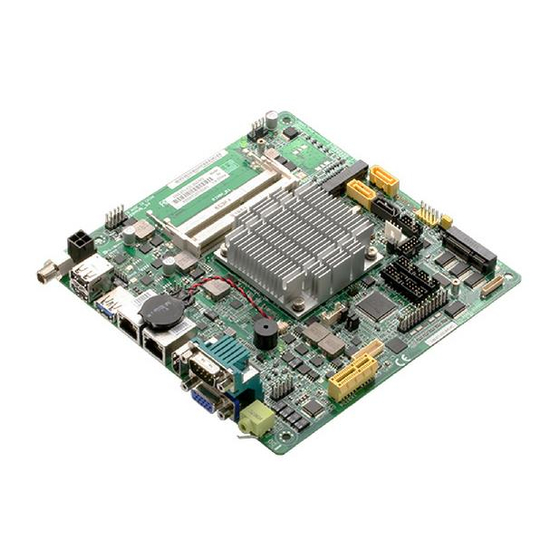
Page 10: Motherboard Layout
DDR3_DIMM_A1 (64bit, 204-pin module) USB3_1 USBHUB_56 MINI_CARD1 LAN1 8111G Place this side LAN2 towards the rear 8111G 1661 of the chassis HDMI1 BATTERY1 1442 SPI1 64Mb INV1 BIOS LED2 COM1 Super KBMS1 AAFP1 LVDS1 AUDIO1 LPT1 CHRONTEL CH7511 PCIEX1_1 EMB-BT1... - Page 11 Connectors/Jumpers/Slots Page 12VDC connector (4-pin EATX_PWR1) 2-14 USB 2.0 connector (10-1 pin USBHUB_34, USBHUB_56 and USBHUB_7) 2-19 SO-DIMM memory slots Standby Power LED (Main_PWR_LED1, SB_PWR_LED2) 2-11 Chassis fan connectors (4-pin CHA_FAN1) 2-15 LVDS panel voltage selection (3-pin J1) 2-21 SATA power connector (SATA_PWR1) 2-17 Minicard connector (MINI_CARD1, MINI_CARD2) 2-19...
-
Page 12: Screw Size
Screw size 2.3.1 Component side EMB-BT1... -
Page 13: Solder Side
2.3.2 Solder side Chapter 2: Motherboard information... -
Page 14: Central Processing Unit (Cpu)
System memory This motherboard comes with two Double Data Rate 3 Low Voltage (DD3L) Small Outline Dual Inline Memory Modules (SO-DIMM) socket. The figure illustrates the location of the DDR3L DIMM socket: DIMM_B1 DIMM_A1 EMB-BT1 204-pin DDR3 SO-DIMM sockets NOTE: Use the SO-DIMM_A1 slot when inserting only one SO-DIMM. EMB-BT1... -
Page 15: Installing And Removing A So-Dimm
2.5.1 Installing and removing a SO-DIMM To install a SO-DIMM To remove a SO-DIMM Chapter 2: Motherboard information... -
Page 16: Jumpers
CLRTC Normal Clear RTC1 (Default) EMB-BT1 Clear RTC RAM To erase the RTC RAM: Turn OFF the computer and unplug the power cord. Move the jumper cap from pins 1-2 (default) to pins 2-3. Keep the cap on pins 2-3 for about 5~10 seconds, then move the cap back to pins 1-2. - Page 17 COM1 Ring/+5V/+12V selector (COM1) +12V Ring (Default) EMB-BT1 COM1 Ring/+5V/+12V Selection Setting Pins +12V Ring (Default) Inverter voltage selection (3-pin J2) +12V (Default) EMB-BT1 Inverter Voltage Selection Setting Pins +12V +5V (Default) Chapter 2: Motherboard information...
- Page 18 Inverter Backlight Control of Inverter selector (3-pin J3) DC CTL PWM CTL (Default) EMB-BT1 Mode Selection for Back Light Control of Inverter Setting Pins DC Voltage Control PWM Control (Default) LVDS panel voltage selection (3-pin J4) (Default) EMB-BT1 LVDS Panel Voltage Selection...
-
Page 19: Onboard Leds
The illustration below shows the location of the onboard LEDs. SB_PWR1 Standby Power Powered Off SB_PWR2 Main Power Main Power Off EMB-BT1 Onboard LEDs Chapter 2: Motherboard information 2-11... -
Page 20: Connectors
LED indications. LAN port LED indications Speed Activity Link ACT/LINK LED SPEED LED Status Description Status Description No link 10 Mbps connection ORANGE Linked ORANGE 100 Mbps connection LAN port BLINKING Data activity GREEN 1 Gbps connection EMB-BT1 2-12... - Page 21 HDMI port. This port is for a High-Definition Multimedia Interface (HDMI) connector, and is HDCP compliant allowing playback of HD DVD, Blu-ray, and other protected content. Serial port (COM2). This port connects a modem, or other devices that conform with serial specification. This serial port also supports RS-232 (COM2 is optional). Line Out port (lime). This port connects to a headphone or a speaker. Video Graphics Adapter (VGA) port.
-
Page 22: Internal Connectors
12VDC power connectors (4-pin EATX_PWR1) This connector is for an EATX power supply plug. The power supply plug is designed to fit this connector in only one orientation. Find the proper orientation and push down firmly until the connector completely fits. EATX_PWR1 PIN 1 EMB-BT1 12VDC power connector IMPORTANT: • For a fully configured system, we recommend that you use a power supply unit (PSU) that complies with ATX 12 V Specification 2.0 (or later version). • DO NOT forget to connect the 4-pin ATX +12V power plug. Otherwise, the system will not have enough power. - Page 23 HD Audio or legacy AC`97 audio standard. Connect one end of the front panel audio I/O module cable to this connector. AAFP PIN 1 HD-audio-compliant Legacy AC’97 pin definition compliant definition EMB-BT1 Front panel audio connector IMPORTANT: We recommend that you connect a high-definition front panel audio module to this connector to avail of the motherboard’s high-definition audio capability. Chapter 2: Motherboard information 2-15...
- Page 24 HDD_LED- PWR_LED+ HDD_LED+ PIN 1 EMB-BT1 System panel connector • System power LED (2-pin PWR_LED) This 2-pin connector is for the system power LED. Connect the chassis power LED cable to this connector. The system power LED lights up when you turn on the system power, and blinks when the system is in sleep mode.
- Page 25 RSATA_RXP2 RSATA_TXP1 RSATA_RXN2 RSATA_TXN1 RSATA_TXN2 RSATA_RXN1 RSATA_TXP2 RSATA_RXP1 EMB-BT1 SATA 6.0Gb/s connectors IMPORTANT: • You must install Windows XP Service Pack 3 or later version before using ® Serial ATA hard disk drives. • When using hot-plug and NCQ, set the SATA Mode Selection item in the BIOS to [AHCI].
- Page 26 LVDS connector (30-pin LVDS1) This connector is for an LCD monitor that supports Low-Voltage Differential Signaling (LVDS) interface. LVDS1 PIN 1 EMB-BT1 LVDS connector Backlight inverter power connector (5-pin INV1) Connect the backlight inverter power cable to this connector. INV1 PIN1...
- Page 27 Minicard connector Use these connectors to connect a Minicard reader. MINI_CARD1 MINI_CARD2 EMB-BT1 MINICARD connectors NOTE: The Mini-card module is purchased separately. 10. USB 2.0 connector (10-1 pin USBHUB_34, USBHUB_56 and USBHUB_7) These USB connectors comply with USB 2.0 specifications. USBHUB_34 PIN 1 USBHUB_7 USBHUB_56 (NC) USB6+...
- Page 28 11. BIOS programmable connector (8-pin SPI) Use this connector to flash the BIOS ROM. PIN 1 EMB-BT1 BIOS Programmable Connector 12. LPT connector (26-1 pin LPT1) The LPT (Line Printing Terminal) connector supports devices such as a printer. LPT is standardized as IEEE 1284, which is the parallel port interface on IBM PC-compatible computers.
- Page 29 PIN 1 PIN 1 COM5 PIN 1 COM6 PIN 1 EMB-BT1 Serial Port Connector NOTE: • The COM module is purchased separately. • COM1 also supports RS-232 / RS-422 / RS-485. See the table below and section 3.3.2 Super IO Configuration for details.
- Page 30 I/O lines are programmable and each I/O pin can be individually programmed to support various devices. DIO1 PIN 1 EMB-BT1 DIO Connector 15. PS/2 keyboard/mouse connector (6-pin KBMS1) This connector is for an IBM PS/2-compatible keyboard or mouse. KBMS1 PIN 1 EMB-BT1 Series PS/2 keyboard/mouse connector EMB-BT1 2-22...
- Page 31 RSATA_RXP2 RSATA_TXP1 RSATA_RXN2 RSATA_TXN1 RSATA_TXN2 RSATA_RXN1 RSATA_TXP2 RSATA_RXP1 EMB-BT1 SATA 3.0Gb/s connectors NOTES: • You must install Windows XP Service Pack 3 or later version before using ® Serial ATA hard disk drives. • When using hot-plug and NCQ, set the SATA Mode Selection item in the BIOS to [AHCI].
- Page 32 EMB-BT1 2-24...
-
Page 33: Chapter 3 Bios Setup
Chapter 3 BIOS setup BIOS setup Use the BIOS Setup to update the BIOS or configure settings. The BIOS screens include navigation keys and help to guide you in using the BIOS Setup program. Entering BIOS Setup at startup To enter BIOS Setup at startup: Press <Delete> during the Power-On Self Test (POST). If you do not press <Delete>, POST continues with its routine. -
Page 34: Menu Bar
3.2.1 System Language [English] Select a system language. 3.2.2 System Date [Day MM/DD/YYYY] Allows you to set the system date. 3.2.3 System Time [HH:MM:SS] Allows you to set the system time. EMB-BT1... -
Page 35: Advanced Menu
Advanced menu The Advanced menu items allow you to change the settings for the CPU and other system devices. Be cautious when changing the settings of the Advanced menu items. Incorrect field values can cause the system to malfunction. 3.3.1 ACPI Settings Enable ACPI Auto Configuration [Disabled] Configuration options: [Enabled] [Disabled] Enable Hibernation [Enabled] Enables or disables hibernate feature (OS/4 Sleep State). - Page 36 Change Settings [Auto] Allows you to select an optimal setting for Super I/O devices. Configuration options: [Auto] [IO=378h; IRQ=5;] [IO=378h; IRQ=5~12;] [IO=278h; IRQ=5~12;] [IO=3BCh; IRQ=5~12;] [IO=378h;] [IO=278h;] [IO=3BCh;] Device Mode [STD Printer Mode] Allows you to select the Printer Port mode. Configuration options: [STD Printer Mode] [SPP Mode] [EPP-1.9 and SPP Mode] [EPP-1.7 and SPP Mode] ERP Function [Enabled] Enable/disable ERP power saving function. Configuration options: [Enabled] [Disabled]. EMB-BT1...
-
Page 37: Hardware Monitor
3.3.3 Hardware Monitor FAN2 Configuration The sub-items in this menu configure available fans on the system. SYS Smart Fan control [Auto by Duty-Cycle] Select Smart Fan control mode. Configuration options: [Auto by RPM] [Auto by Duty-Cycle] [Manual by RPM] [Manual by Duty-Cycle] Target Temp. Sensor Configuration options: [CPU Temperature] [SYS Temperature] Temperature Bound 1~4 Input temperature setting. Input value range: [0~127] Segment 1~5 Speed (PWM) Input fan speed in PWM duty-cycle. Input value range: [0~100] The following item replaces Segment 1~5 Speed (PWM) when SYS Smart Fan Control is set to Auto by RPM. -
Page 38: Cpu Configuration
Intel Virtualization Technology [Disabled] [Enabled] Allows a hardware platform to run multiple operating systems separately and simultaneously, enabling one system to virtually function as several systems. [Disabled] Disables this function. Power Technology [Energy Efficient] [Disable] Disables power management features. [Energy Efficient] Uses default power management settings. [Custom] Customize power management. EMB-BT1... - Page 39 The following items appear only when you set the Power Technology item to [Custom] EIST [Enabled] Allows you to enable or disable Enhanced Intel SpeedStep Technology. ® [Disabled] The CPU runs at its default speed. [Enabled] The operating system controls the CPU speed. P-STATE Coordination [HW_ALL] Allows you to change P-STATE Coordination type.
-
Page 40: Ppm Configuration
SpeedStep Technology. ® [Disabled] The CPU runs at its default speed. [Enabled] The operating system controls the CPU speed. CPU C state Report [Enabled] Configuration options: [Enabled] [Disabled] Enhanced C state [Enabled] Configuration options: [Enabled] [Disabled] Max CPU C-state [C7] Configure supported Max C state. Configuration options: [C7] [C6] [C1] S0ix [Enabled] Configuration options: [Enabled] [Disabled] EMB-BT1... -
Page 41: Thermal Configuration
3.3.6 Thermal Configuration Critical Trip Point [90 C] Specify the temperature at which the OS will shut down the system. Configuration options: [90 C] [87 C] [85 C] [79 C] [71 C] [63 C] [55 C] [47 C] [39 C] [31 C] [23 C] [15 C] Passive Trip Point [85 C] Specify the temperature at which the OS will begin adjusting the processor. Configuration options: [90 C] [87 C] [85 C] [79 C] [71 C] [63 C] [55 C] [47 C] [39 C] [31 C] [23 C] [15 C] DPTF [Disabled]... - Page 42 DPPM [Enabled] Configuration options: [Enabled] [Disabled] CLPM [OS level] Current Low Power Mode. Configuration options: [OS level] [Application specific] [Enabled] [Disabled] DPPM [Enabled] Configuration options: [Enabled] [Disabled] DPTF processor [DIsabled] Enables or disables Processor Participant Device. Configuration options: [Enabled] [Disabled] CPU/Ambient/DDR Sensors [Enabled] Enables or disables CPU/Ambient/DDR Temperature Sensors. Configuration options: [Enabled] [Disabled] Charger/Display/Power Participant [Enabled] Enables or disables Charger Participant Device. Configuration options: [Enabled] [Disabled] EMB-BT1 3-10...
-
Page 43: Ide Configuration
3.3.7 IDE Configuration Serial-ATA (SATA) [Enabled] Allows you to enable or disable Serial-ATA. Configuration options: [Enabled] [Disabled] SATA Test Mode [Disabled] Allows you to enable or disable SATA Test Mode. Configuration options: [Enabled] [Disabled] SATA Mode [AHCI Mode] Allows you to set the SATA configuration. [AHCI Mode] Set to [AHCI] when you want the SATA hard disk drives to use AHCI (Advanced Host Controller Interface). AHCI allows the onboard storage driver to enable advanced Serial ATA features that increases storage performance on random workloads by allowing the drive to internally optimize the order of commands. -
Page 44: System Component
PCI-X Latency Timer [64 PCI Bus Clocks] Configuration options: [32 PCI Bus Clocks]~[248 PCI Bus Clocks] VGA Palette Snoop [Disabled] Configuration options: [Enabled] [Disabled] VGA Palette Snoop [Disabled] Configuration options: [Enabled] [Disabled] PERR# Generation [Disabled] Configuration options: [Enabled] [Disabled] SERR# Generation [Disabled] Configuration options: [Enabled] [Disabled] Above 4G Decoding [Disabled] Configuration options: [Enabled] [Disabled] SR-IOV Support [Disabled] Configuration options: [Enabled] [Disabled] PCI Express Settings Relaxed Ordering [Disabled] Configuration options: [Enabled] [Disabled] EMB-BT1 3-12... - Page 45 Extended Tag [Enabled] When enabled, the PCI device uses an 9-bit tag field as requester. Configuration options: [Enabled] [Disabled] No Snoop [Enabled] Configuration options: [Enabled] [Disabled] Maximum Payload [Auto] Set maximum payload of PCI Express Device. Configuration options: [Auto] [128 Bytes] [256 Bytes] [512 bytes] [1024 Bytes] [2048 Bytes] [4096 Bytes] Maximum Read Request [Auto] Set maximum read request size of PCI Express Device. Configuration options: [Auto] [128 Bytes] [256 Bytes] [512 bytes] [1024 Bytes] [2048 Bytes] [4096 Bytes] ASPM Support [Disabled] Configuration options: [Auto] [Disabled] [Force L0s]...
- Page 46 [Enabled] [Disabled] End-End TLP Prefix Blocking [Disabled] Configuration options: [Enabled] [Disabled] Target Link Speed [Auto] Configuration options: [Auto] [Force to 2.5 GT/s] [Force to 5.0 GT/s] Clock Power Management [Disabled] Configuration options: [Enabled] [Disabled] Compliance SOS [Disabled] Configuration options: [Enabled] [Disabled] Hardware Autonomous Width [Disabled] Set to Disabled to prevent hardware from changing link width. Configuration options: [Enabled] [Disabled] Hardware Autonomous Speed [Disabled] Set to Disabled to prevent hardware from changing link speed. Configuration options: [Enabled] [Disabled] EMB-BT1 3-14...
-
Page 47: Dynamic Digital Io
3.3.11 Dynamic Digital IO The items in this menu allow you to modify Digital IO settings. GPIO 0~3 Direction [Input] Set GPIO data flow as Input or Output. Configuration options: [Input] [Output] GPO 4~7 Direction [Output] Set GPO0 data flow as Input or Output. Configuration options: [Input] [Output] Output Level [High] Configuration options: [High][Low] 3.3.12 Trusted Computing Security Device Support [Disabled] Configuration options: [Enabled] [Disabled] 3.3.13 USB Configuration The USB Devices item lists auto-detected values. -
Page 48: Platform Trust Technology
[20 sec] [30 sec] [40 sec] Device power-up delay [Auto] Configuration options: [Auto] [Manual] The following item is available when Device power-up delay is set to Manual. Device power-up delay in seconds [5] Configuration options: [1~40 secondsl] 3.3.13 Platform Trust Technology TPM [Disabled] Configuration options: [Enabled] [Disabled] EMB-BT1 3-16... -
Page 49: Security Configuration
3.3.14 Security Configuration TXE / TXE HMRFPO / TXE Firmware Update / TXE EOP Message / TXE Unconfiguration Perform Configure Intel TXE settings. Configuration options: [Enabled] [Disabled] ® Intel(R) AT / Intel(R) AT Platform PBA / Intel(R) AT Suspend Mode Configure Intel Anti-Theft Technology. Configuration options: [Enabled] [Disabled] ® Chipset menu The Chipset menu items allow you to change configuration options for the North Bridge and South Bridge. 3.4.1 North Bridge Intel IGD Configuration... - Page 50 [1920x1200, 48bit, 60Hz] [Reserved for customization] Force Lid Status [On] Configuration options: [On] [Off] BIA [Auto] Configuration options: [Auto] [LEVEL1] [LEVEL2] [LEVEL3] [LEVEL4] [LEVEL5] [Disabled] ALS Support [Disabled] Configuration options: [Enabled] [Disabled] IGD Flat Panel options [Auto] Select flat panel resolution.Configuration options: [640x480] [800x600] [1024x768] [1280x1024] [1366x768] [1680x1050] [1600x1200] [1280x800] Panel Scaling [Auto] Configuration options: [Auto] [Centering] [Stretching] Graphics Management Control Max TOLUD Configuration options: [Dynamic] [1 GB] ~ [3GB] EMB-BT1 3-18...
-
Page 51: South Bridge
3.4.2 South Bridge Azalia HD Audio LPE Audio Support [Disabled] Select LPE Audio ACPI mode or PCI mode. Configuration options: [Disabled] [LPE Audio PCI mode] [LPE Audio ACPI mode] Audio Controller [Enabled] Configuration options: [Disabled] [Enabled] Azalia VCi Enable [Enabled] Configuration options: [Disabled] [Enabled] Azalia Docking Support Enable [Disabled] Configuration options: [Disabled] [Enabled] Azalia PME Enable [Enabled] Configuration options: [Disabled] [Enabled] Azalia HDMI Codec [Enabled] Configuration options: [Disabled] [Enabled] USB Configuration USB OTG Support [Disabled]... - Page 52 AC power loss. Serial IRQ Mode [Continuous] Configuration options: [Quiet] [Continuous] BIOS Read/Write Protection [Enabled] Allows you to enable or disable BIOS SPI region read/write protection. Configuration options: [Enabled] [Disabled] Device Mode [RS232] Allows you to enable or disable BIOS SPI region read/write protection. Configuration options: [RS232] [RS422] [RS485] EMB-BT1 3-20...
-
Page 53: Security Menu
Security menu The Security menu items allow you to change the system security settings. 3.5.1 Administrator Password If you have set an administrator password, we recommend that you enter the administrator password for accessing the system. Otherwise, you might be able to see or change only selected fields in the BIOS setup program. -
Page 54: Boot Menu
Input number of seconds to wait for setup activation key. Bootup NumLock State [On] [On] Sets the power-on state of the NumLock to [On]. [Off] Sets the power-on state of the NumLock to [Off]. Quiet Boot [Disabled] Configuration options: [Disabled] [Enabled] Boot Option [Disabled] Set system boot order. Configuration options: [Disabled] [UEFI: Built-in EFI Shell] EMB-BT1 3-22... -
Page 55: Save & Exit Menu
Save & Exit menu Save Changes and Exit Once you are finished making your selections, choose this option from the Exit menu to ensure the values you selected are saved. When you select this option, a confirmation window appears. Select Yes to save changes and exit. Discard Changes and Reset This option allows you to exit the Setup program without saving your changes. When you select this option or if you press <Esc>, a confirmation window appears. - Page 56 EMB-BT1 3-24...
-
Page 57: Appendix
Check local regulations for disposal of electronic products. DO NOT throw the mercury-containing button cell battery in municipal waste. This symbol of the crossed out wheeled bin indicates that the battery should not be placed in municipal waste. EMB-BT1... - Page 58 印 刷 電 路 板 及 其 × ○ ○ ○ ○ ○ 電子組件 外 部 信 號 連 接 頭 × ○ ○ ○ ○ ○ 及線材 ○: 表示該有毒有害物質在該部件所有均質材料中的含量均在 SJ/T 11363- 2006 標准規定的限量要求以下。 ×: 表示該有毒有害物質至少在該部件的某一均質材料中的含量超出 SJ/T 11363-2006 標准規定的限量要求,然該部件仍符合歐盟指令 2002/95/ EC 的規范。 備註:此產品所標示之環保使用期限,係指在一般正常使用狀況下。 EMB-BT1...
Need help?
Do you have a question about the EMB-BT1 and is the answer not in the manual?
Questions and answers