
Subscribe to Our Youtube Channel
Related Manuals for Aaeon EMB-CV1 series


Summary of Contents for Aaeon EMB-CV1 series
- Page 1 I n d u s t r i a l M o t h e r b o a r d E M B - C V 1 s e r i e s EMB-CV1 series Manual 5 November 2015...
- Page 2 I n d u s t r i a l M o t h e r b o a r d E M B - C V 1 s e r i e s Copyright Notice This document is copyrighted, 2015. All rights are reserved. The original manufacturer reserves the right to make improvements to the products described in this manual at any time without notice.
- Page 3 I n d u s t r i a l M o t h e r b o a r d E M B - C V 1 s e r i e s Acknowledgments All other products’ name or trademarks are properties of their respective owners.
- Page 4 I n d u s t r i a l M o t h e r b o a r d E M B - C V 1 s e r i e s Packing List (Standard, not bulk pack) Before you begin installing your card, please make sure that the following materials have been shipped: ...
-
Page 5: Table Of Contents
I n d u s t r i a l M o t h e r b o a r d E M B - C V 1 s e r i e s Contents Chapter 1 General Information 1.1 Features ..............1-2 1.2 Specifications ............ - Page 6 I n d u s t r i a l M o t h e r b o a r d E M B - C V 1 s e r i e s 2.15 +12V AUX Power Connector (CON2) ....2-11 2.16 CPU/SYSTEM FAN Connector (CPU_FAN/CHA_FAN) ..................
- Page 7 I n d u s t r i a l M o t h e r b o a r d E M B - C V 1 s e r i e s Appendix A Programming The Watchdog Timer A.1 Programming ............
-
Page 8: Chapter 1 General Information
I n d u s t r i a l M o t h e r b o a r d E M B - C V 1 s e r i e s Chapter General Information 1- 1 Chapter 1 General Information... -
Page 9: Features
I n d u s t r i a l M o t h e r b o a r d E M B - C V 1 s e r i e s 1.1 Features ® Atom™ D2550 Processor ... -
Page 10: Specifications
I n d u s t r i a l M o t h e r b o a r d E M B - C V 1 s e r i e s 1.2 Specifications System ® Processor Intel Atom™... - Page 11 I n d u s t r i a l M o t h e r b o a r d E M B - C V 1 s e r i e s Operating Temperature 32˚F~ 140˚F (0˚C ~ 60˚C) ...
-
Page 12: Chapter 2 Quick Installation Guide
I n d u s t r i a l M o t h e r b o a r d E M B - C V 1 s e r i e s Chapter Quick Installation Guide 2 - 1 Chapter 2 Quick Installation Guide... -
Page 13: Safety Precautions
I n d u s t r i a l M o t h e r b o a r d E M B - C V 1 s e r i e s 2.1 Safety Precautions Always completely disconnect the power cord from your board whenever you are working on it. -
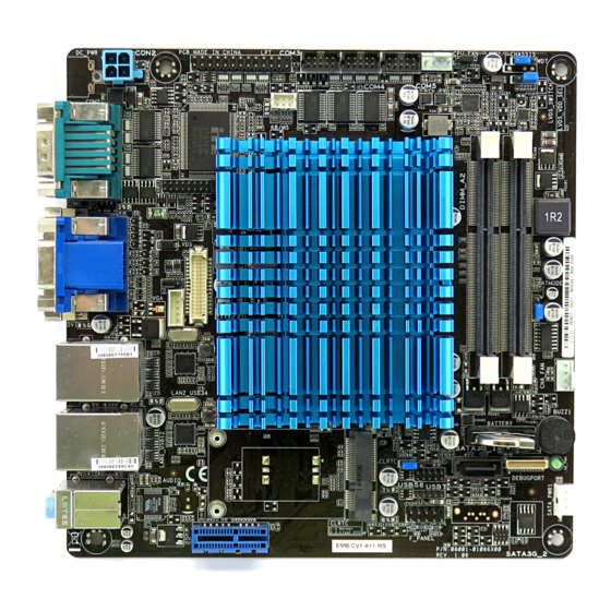
Page 14: Location Of Connectors And Jumpers
I n d u s t r i a l M o t h e r b o a r d E M B - C V 1 s e r i e s 2.2 Location of Connectors and Jumpers NOTE: If choose m-SATA SKU, SATA3G_2 port, mini card and SIM card slot will be disable. -
Page 15: Mechanical Drawing
I n d u s t r i a l M o t h e r b o a r d E M B - C V 1 s e r i e s 2.3 Mechanical Drawing Component Side 2 - 4 Chapter 2 Quick Installation Guide... - Page 16 I n d u s t r i a l M o t h e r b o a r d E M B - C V 1 s e r i e s Solder Side 2 - 5 Chapter 2 Quick Installation Guide...
-
Page 17: List Of Jumpers
I n d u s t r i a l M o t h e r b o a r d E M B - C V 1 s e r i e s 2.4 List of Jumpers The board has a number of jumpers that allow you to configure your system to suit your application. -
Page 18: List Of Connectors
I n d u s t r i a l M o t h e r b o a r d E M B - C V 1 s e r i e s 2.5 List of Connectors The board has a number of connectors that allow you to configure your system to suit your application. - Page 19 I n d u s t r i a l M o t h e r b o a r d E M B - C V 1 s e r i e s USB56 USB 5 & 6 Pin Header USB7 USB 7 Pin Header WLAN...
-
Page 20: Setting Jumpers
I n d u s t r i a l M o t h e r b o a r d E M B - C V 1 s e r i e s 2.6 Setting Jumpers You configure your card to match the needs of your application by setting jumpers. -
Page 21: At/Atx Mode Selection (Atmode)
I n d u s t r i a l M o t h e r b o a r d E M B - C V 1 s e r i e s 2.7 AT/ATX Mode Selection (ATMODE) ATOMODE Function Close 1-2 Close 2-3... -
Page 22: Lvds Function Enable (Lvds_Switch)
I n d u s t r i a l M o t h e r b o a r d E M B - C V 1 s e r i e s 2.12 LVDS function Enable (LVDS_SWITCH) LVDS_SWITCH Function Close 1-2 Disable... -
Page 23: Com3/Com4/Com5 Rs232 Serial Port Pin Header
I n d u s t r i a l M o t h e r b o a r d E M B - C V 1 s e r i e s 2.17 COM3/COM4/COM5 RS-232 Serial Port PIN HEADER (COM3/COM4/COM5) Signal Signal... -
Page 24: Com2 Rs-232/422/485 Connector
I n d u s t r i a l M o t h e r b o a r d E M B - C V 1 s e r i e s 2.19 COM2 RS-232/422/485 connector Signal Signal DCD (422TXD-/485DATA-) RXD (422RXD+) TXD (422TXD+/485DATA+) -
Page 25: Lvds Panel Power Connector (Lcd_Power)
I n d u s t r i a l M o t h e r b o a r d E M B - C V 1 s e r i e s 2.22 LVDS Panel Power Connector (LCD_POWER) Signal Signal Panel Power... -
Page 26: Lvds Panel Connector (Lvds)
I n d u s t r i a l M o t h e r b o a r d E M B - C V 1 s e r i e s 2.24 LVDS Panel Connector (LVDS) Signal Signal Panel power DDC_DATA... -
Page 27: Serial Ata Power Connector (Sata_Pwr1)
I n d u s t r i a l M o t h e r b o a r d E M B - C V 1 s e r i e s DVI-D Audio 2.25 Serial ATA Power Connector (SATA_PWR1) Signal Signal +12V... -
Page 28: Usb 7 Pin Header (Usb7)
I n d u s t r i a l M o t h e r b o a r d E M B - C V 1 s e r i e s 2.27 USB 7 PIN HEADER (USB7) Signal USBD- USBD+... -
Page 29: Chapter 3 Ami Bios Setup
I n d u s t r i a l M o t h e r b o a r d E M B - C V 1 s e r i e s Chapter BIOS Setup Chapter 3 AMI BIOS Setup 3-1... -
Page 30: System Test And Initialization
I n d u s t r i a l M o t h e r b o a r d E M B - C V 1 s e r i e s 3.1 System Test and Initialization These routines test and initialize board hardware. If the routines encounter an error during the tests, you will either hear a few short beeps or see an error message on the screen. -
Page 31: Ami Bios Setup
I n d u s t r i a l M o t h e r b o a r d E M B - C V 1 s e r i e s 3.2 AMI BIOS Setup AMI BIOS ROM has a built-in Setup program that allows users to modify the basic system configuration. -
Page 32: Chapter 4 Driver Installation
I n d u s t r i a l M o t h e r b o a r d E M B - C V 1 s e r i e s Chapter Driver Installation 4 -1 Chapter 4 Driver Installation... - Page 33 I n d u s t r i a l M o t h e r b o a r d E M B - C V 1 s e r i e s The EMB-CV1 comes with an Autorun CD-ROM that contains all drivers and utilities that can help you to install the driver automatically.
- Page 34 I n d u s t r i a l M o t h e r b o a r d E M B - C V 1 s e r i e s 4.1 Installation: Insert the EMB-CV1 CD-ROM into the CD-ROM drive. And install the drivers from Step 1 to Step 5 in order.
- Page 35 I n d u s t r i a l M o t h e r b o a r d E M B - C V 1 s e r i e s 2. Follow the instructions that the window shows 3.
- Page 36 I n d u s t r i a l M o t h e r b o a r d E M B - C V 1 s e r i e s Appendix Programming the Watchdog Timer Appendix A Programming the Watchdog Timer A-1...
-
Page 37: A.1 Programming
I n d u s t r i a l M o t h e r b o a r d E M B - C V 1 s e r i e s A.1 Programming EMB-CV1 utilizes ITE 8783 chipset as its watchdog timer controller. - Page 38 I n d u s t r i a l M o t h e r b o a r d E M B - C V 1 s e r i e s There are three steps to complete the configuration setup: (1) Enter the MB PnP Mode;...
- Page 39 I n d u s t r i a l M o t h e r b o a r d E M B - C V 1 s e r i e s WatchDog Timer Configuration Registers Configure Control (Index=02h) This register is write only.
- Page 40 I n d u s t r i a l M o t h e r b o a r d E M B - C V 1 s e r i e s Watch Dog Timer 1, 2, 3 Configuration Register (Index=72h, 82h, 92h Default=001s0000b) Watch Dog Timer 1,2,3 Time-Out Value (LSB) Register (Index=73h,83h,93h, Default=38h)
-
Page 41: A.2 Ite8783 Watchdog Timer Initial Program
I n d u s t r i a l M o t h e r b o a r d E M B - C V 1 s e r i e s A.2 ITE8783 Watchdog Timer Initial Program .MODEL SMALL .CODE Main:... - Page 42 I n d u s t r i a l M o t h e r b o a r d E M B - C V 1 s e r i e s call Superio_Set_Reg ; game port enable mov cl, 9 call Set_Logic_Device Initial_OK:...
- Page 43 I n d u s t r i a l M o t h e r b o a r d E M B - C V 1 s e r i e s CALL Write_Configuration_Data Exit_Configuration_Mode ENDP Check_Chip PROC NEAR MOV AL,20h CALL Read_Configuration_Data CMP AL,87h...
- Page 44 I n d u s t r i a l M o t h e r b o a r d E M B - C V 1 s e r i e s OUT DX,AL MOV DX,WORD PTR CS:[Cfg_Port+06h] IN AL,DX Read_Configuration_Data ENDP Write_Configuration_Data PROC NEAR...
- Page 45 I n d u s t r i a l M o t h e r b o a r d E M B - C V 1 s e r i e s Set_Logic_Device proc near push ax push cx xchg al,cl mov cl,07h call Superio_Set_Reg...
- Page 46 I n d u s t r i a l M o t h e r b o a r d E M B - C V 1 s e r i e s Appendix Mating Connector B - 1 Appendix B Mating Connector...
-
Page 47: B.1 List Of Mating Connectors And Cables
I n d u s t r i a l M o t h e r b o a r d E M B - C V 1 s e r i e s B.1 List of Mating Connectors and Cables The table notes mating connectors and available cables. - Page 48 I n d u s t r i a l M o t h e r b o a r d E M B - C V 1 s e r i e s WAFER HD 4P S/T 2.54MM CPU FAN CPU_FAN PINREX L-GRAY...
- Page 49 I n d u s t r i a l M o t h e r b o a r d E M B - C V 1 s e r i e s BLUE E-MOVE/EE0360 -1GGZ-00H [GA].DIP (TF)WAFER.4P.1 Serial ATA 80D.(M).2.5mm.
Need help?
Do you have a question about the EMB-CV1 series and is the answer not in the manual?
Questions and answers