Table of Contents
Advertisement
Quick Links
Advertisement
Table of Contents

Related Manuals for Aaeon EMB-Q77A


Summary of Contents for Aaeon EMB-Q77A
- Page 1 EMB-Q77A...
- Page 2 E8383 First Edition May 2013 Copyright Notice This document is copyrighted, 2013. All rights are reserved. The original manufacturer reserves the right to make improvements to the products described in this manual at any time without notice. No part of this manual may be reproduced, copied, translated, or transmitted in any form or by any means without the prior written permission of the original manufacturer.
-
Page 3: Table Of Contents
Contents Chapter 1 Product overview Package contents ................. 1-1 Features ..................1-1 1.3 Specifications ................1-2 Chapter 2 Motherboard information Before you proceed ..............2-1 Motherboard layout ..............2-2 Screw size ..................2-4 2.3.1 Component side .............. 2-4 2.3.2 Solder side ..............2-5 Central Processing Unit (CPU) ........... - Page 4 Advanced menu ................3-4 3.3.1 Trusted Computing ............3-4 3.3.2 CPU Configuration ............3-5 3.3.3 SATA Configuration ............3-6 3.3.4 System Agent Configuration ........... 3-7 3.3.5 Intel TXT(LT) Configuration ..........3-8 3.3.6 AMT Configuration ............3-8 3.3.7 USB Configuration ............3-9 3.3.8 Onboard Devices Configuration ........3-10 3.3.9 APM ................3-12 3.3.10 Network Stack ...............
-
Page 5: Chapter 1 Product Overview
Chapter 1 Product overview Package contents Check your industrial motherboard package for the following items. 1 x Industrial Motherboard 1 x SATA Cable 1 x I/O Shield 1 x Support CD If any of the above items is damaged or missing, contact your distributor or sales representative immediately. -
Page 6: Specifications
6.7 in. x 6.7 in. (17.0 cm x 17.0 cm) Gross weight 0.94 lb (0.426 Kg) Operating F~140 F (0 C~60 temperature Storage temperature F~185 F (-40 C~85 Operating humidity 0%~90% relative humidity, non-condensing Power compliance Compliant with Eup/ErP Certificate CE/FCC (continued on the next page) EMB-Q77A... - Page 7 DISPLAY Chipset Intel Graphics Media Accelerator ® Resolution Up to 1920x1200@60Hz for DVI-D Up to 1920x1200@60Hz for DVI-I Output interface 1 x DVI-D 1 x DVI-I Storage 2 x SATA 6.0Gb/s ports 2 x SATA 3.0Gb/s ports RAID 0 / 1 / 5 / 10 Serial port 1 x RS-232/422/485 supports 5V/12V/RI option (COM1, box header) 1 x RS-232 (COM2, box header)
- Page 8 EMB-Q77A...
-
Page 9: Chapter 2 Motherboard Information
Chapter 2 Motherboard information Before you proceed Take note of the following precautions before you install motherboard components or change any motherboard settings. CAUTION! • Unplug the power cord from the wall socket before touching any component. • Before handling components, use a grounded wrist strap or touch a safely grounded object or a metal object, such as the power supply case, to avoid damaging them due to static electricity. -
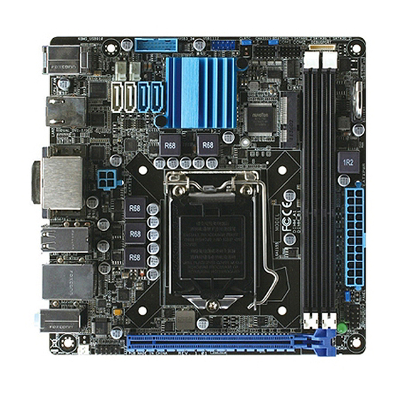
Page 10: Motherboard Layout
17.0cm(6.7in) CHASSIS CLRTC USB1112 USB3_34 KBMS_USB910 COM1 COM2 COM1 Intel ® _VSET Intel 82583V LAN2 Super 1442 1442 EATX12V Place this side towards the rear of the chassis USB5678 LAN1_USB3_12 Intel DIS_ME 82579LM AUDIO SB_PWR PCIEX16 AAFP INT_SPKR1 EMB-Q77A... - Page 11 Connectors/Jumpers/Slots Page CPU and system fan connectors (4-pin CPU_FAN, 4-pin CHA_FAN) 2-20 USB 3.0 connector (20-1 pin USB3_34) 2-24 Serial ATA 3.0Gb/s connectors (7-pin SATA3G_1, SATA3G_2) 2-23 USB 2.0 connector (10-1 pin USB1112) 2-24 Clear RTC RAM (CLRTC) 2-13 Chassis intrusion connector (4-1 pin CHASSIS) 2-21 Serial port connectors (10-1 pin COM1, 10-1 COM2) 2-25...
-
Page 12: Screw Size
Screw size 2.3.1 Component side EMB-Q77A... -
Page 13: Solder Side
2.3.2 Solder side Chapter 2: Motherboard information... -
Page 14: Central Processing Unit (Cpu)
Intel® 3rd/2nd Generation Core™ i7 / Core™ i5 / Core™ i3 / Pentium / Celeron ® ® processors. EMB-Q77A CPU socket LGA1155 IMPORTANT: Unplug all power cables before installing the CPU. CAUTION! • Upon purchase of the motherboard, ensure that the PnP cap is on the socket and the socket contacts are not bent. -
Page 15: Installing The Cpu
2.4.1 Installing the CPU CAUTION! The LGA1156 CPU is incompatible with the LGA1155 socket. DO NOT install a LGA1156 CPU on the LGA1155 socket. Chapter 2: Motherboard information... - Page 16 EMB-Q77A...
-
Page 17: Cpu Heatsink And Fan Assembly Installation
2.4.2 CPU heatsink and fan assembly installation CAUTION! Apply the Thermal Interface Material to the CPU heatsink and CPU before you install the heatsink and fan if necessary. To install the CPU heatsink and fan assembly Chapter 2: Motherboard information... - Page 18 To uninstall the CPU heatsink and fan assembly EMB-Q77A 2-10...
-
Page 19: System Memory
DDR2 DIMM socket. DDR3 modules are developed for better performance with less power consumption. The figure below illustrates the location of the DDR3 DIMM sockets: Channel Sockets Channel A DIMM_A1 Channel B DIMM_B1 EMB-Q77A 240-pin DDR3 DIMM sockets Chapter 2: Motherboard information 2-11... -
Page 20: Installing A Dimm
2.5.1 Installing a DIMM To remove a DIMM EMB-Q77A 2-12... -
Page 21: Jumpers
CLRTC RTC Batt. Clear CMOS (Default) EMB-Q77A Clear RTC RAM To erase the RTC RAM: Turn OFF the computer and unplug the power cord. Move the jumper cap from pins 1-2 (default) to pins 2-3. Keep the cap on pins 2-3 for about 5~10 seconds, then move the cap back to pins 1-2. - Page 22 Management Engine (ME) boot from ® recovery mode when ME become corrupted. DIS_ME ME Enable ME Disable (Default) EMB-Q77A Intel ME jumper ® COM1 Ring/+5V/+12V selection (COM1_VSET) COM1_VSET PIN 1 EMB-Q77A COM VSET connector Setting Pins +12V Ring (Default) EMB-Q77A 2-14...
-
Page 23: Onboard Leds
The illustration below shows the location of the onboard LED. SB_PWR Standby Power Powered Off EMB-Q77A Onboard LED Chapter 2: Motherboard information 2-15... -
Page 24: Connectors
LED indications. LAN1 port LED indications Speed Activity Link ACT/LINK LED SPEED LED Status Description Status Description No link 10 Mbps connection ORANGE Linked ORANGE 100 Mbps connection LAN port BLINKING Data activity GREEN 1 Gbps connection EMB-Q77A 2-16... - Page 25 Line In port (light blue). This port connects the tape, CD, DVD player, or other audio sources. Line Out port (lime). This port connects to a headphone or a speaker. In a 4-channel, 6-channel and 8-channel configurations, the function of this port becomes Front Speaker Out. Microphone port (pink). This port connects a microphone. NOTE: Refer to the audio configuration table below for the function of the audio ports in the 2, 4, 6 or 8-channel configuration.
- Page 26 No link 10 Mbps connection GREEN Linked ORANGE 100 Mbps connection LAN port BLINKING Data activity GREEN 1 Gbps connection 11. USB 2.0 ports. These two 4-pin Universal Serial Bus (USB) ports are available for connecting USB 2.0/1.1 devices. EMB-Q77A 2-18...
-
Page 27: Internal Connectors
+5 VDC +5 VDC PS_ON# +3.3VDC -12VDC +3.3VDC +3.3VDC PIN 1 EMB-Q77A ATX power connectors IMPORTANT: • For a fully configured system, we recommend that you use a power supply unit (PSU) that complies with ATX 12 V Specification 2.0 (or later version) and provides a minimum power of 230W. • DO NOT forget to connect the 4-pin ATX +12V power plug. Otherwise, the system will not have enough power. - Page 28 CPU_FAN CHA_FAN SENSE SENSE EMB-Q77A CPU fan connector CAUTION: Do not forget to connect the fan cables to the fan connectors. Insufficient air flow inside the system may damage the motherboard components. These are not jumpers! Do not place jumper caps on the fan connectors! NOTE: The CPU_FAN connector supports a CPU fan of maximum 2A (24 W) fan power.
- Page 29 HD Audio or legacy AC`97 audio standard. Connect one end of the front panel audio I/O module cable to this connector. AAFP PIN 1 HD-audio-compliant Legacy AC’97 pin definition compliant definition EMB-Q77A Front panel audio connector IMPORTANT: • We recommend that you connect a high-definition front panel audio module to this connector to avail of the motherboard’s high-definition audio capability. • If you want to connect a high-definition front panel audio module to this connector, set the Front Panel Type item in the BIOS setup to [HD];...
- Page 30 PLED- PLED+ HDD_LED+ PIN 1 EMB-Q77A System panel connector • System power LED (2-pin PWR_LED) This 2-pin connector is for the system power LED. Connect the chassis power LED cable to this connector. The system power LED lights up when you turn on the system power, and blinks when the system is in sleep mode.
- Page 31 Serial ATA 3.0Gb/s connectors (7-pin SATA3G_1, SATA3G_2) These connectors connect to Serial ATA 3.0 Gb/s hard disk drives and optical drives via Serial ATA 3.0 Gb/s signal cables. EMB-Q77A SATA 3.0Gb/s connectors NOTES: • You must install Windows XP Service Pack 3 or later version before using ®...
- Page 32 3.0 front panel ports. With an installed USB 3.0 module, you can enjoy all the benefits of USB 3.0 including faster data transfer speeds of up to 5Gbps, faster charging time for USB-chargeable devices, optimized power efficiency, and backward compatibility with USB 2.0. USB3_34 PIN 1 PIN 11 EMB-Q77A USB3.0 Front panel connector NOTES: • The USB module cable is purchased separately. • Due to Intel limitations, USB3_34 is only supported in Windows ®...
- Page 33 480 Mbps connection speed. USB1112 PIN 1 EMB-Q77A USB2.0 connector Never connect a 1394 cable to the USB connector. Doing so will damage the motherboard. The USB module cable is purchased separately. Chapter 2: Motherboard information...
- Page 34 These connectors are for serial (COM) ports. Connect the serial port module cables to these connectors, then install the module to a slot opening at the back of the system chassis. COM1 COM2 PIN 1 PIN 1 EMB-Q77A Serial port connector Signal Signal DCD (422TXD-/485DATA-) RXD (422RXD+) TXD (422TXD+/485DATA+) DTR (422RXD-) RI/+12V/+5V N.C.
- Page 35 The 4-pin connector is for the chassis-mounted system warning speaker. The speaker allows you to hear system beeps and warnings. SPEAKER PIN 1 Speaker Out EMB-Q77A Speaker Out Connector 12. Minicard connector Use this connector to connect a Minicard reader. MINICARD EMB-Q77A MINICARD connector 13.
- Page 36 EMB-Q77A 2-28...
-
Page 37: Chapter 3 Bios Setup
Chapter 3 BIOS setup BIOS setup program Use the BIOS Setup program to update the BIOS or configure its parameters. The BIOS screens include navigation keys and brief online help to guide you in using the BIOS Setup program. Entering BIOS Setup at startup To enter BIOS Setup at startup: Press <Delete> during the Power-On Self Test (POST). If you do not press <Delete>, POST continues with its routine. -
Page 38: Bios Menu Screen
For updating the BIOS and viewing DRAM SPD Information. Exit For selecting the exit options and loading default settings. To select an item on the menu bar, press the right or left arrow key on the keyboard until the desired item is highlighted. EMB-Q77A... -
Page 39: Main Menu
Main menu The Main menu provides you an overview of the basic system information, and allows you to set the system date, time, language, and security settings. 3.2.1 System Language [English] System language default is set to English. 3.2.2 System Date [Day MM/DD/YYYY] Allows you to set the system date. -
Page 40: Advanced Menu
Be cautious when changing the settings of the Advanced menu items. Incorrect field values can cause the system to malfunction. 3.3.1 Trusted Computing This item appears only when a TPM module is connected to the motherboard and allows you to change TPM settings. TPM Support [Enabled] Allows you to enable or disable TPM support. Configuration options: [Disabled] [Enabled] TPM State [Enabled] Allows you to enable or disable security devices. Configuration options: [Disabled] [Enabled] EMB-Q77A... -
Page 41: Cpu Configuration
3.3.2 CPU Configuration The items in this menu show the CPU-related information that the BIOS automatically detects. The items shown in the submenu may be different due to the CPU installed. Active Processor Cores [All] Allows you to choose the number of CPU cores to activate in each processor package. Configuration options: [All] [1] [2] [3] Configuration options for active processor cores are dependent on the installed CPU. -
Page 42: Sata Configuration
Set to [RAID] when you want to create a RAID configuration from the SATA hard disk drives. Hot Plug [Disabled] (SATA6G_1 ~ SATA6G_2; SATA3G_1 ~ SATA3G_2; mSATA) These items appear only when you set the SATA Mode Selection item to [AHCI] or [RAID], and allow you to enable/disable SATA Hot Plug Support. Configuration options: [Disabled] [Enabled] EMB-Q77A... -
Page 43: System Agent Configuration
3.3.4 System Agent Configuration VT-d [Disabled] Allows you to enable virtualization technology function on memory control hub. [Enabled] Enables the function. [Disabled] Disables this function. Graphics Configuration Primary Display [Auto] Allows you to decide which graphics controller to use as the primary boot device. Configuration options: [Auto] [iGPU] [PCIE] iGPU Memory [Auto] Allows you to select the amount of system memory allocated to DVMT 5.0... -
Page 44: Intel Txt(Lt) Configuration
Allow you to enable or disable the Intel Active Management Technology (AMT) in ® the BIOS extension. Configuration options: [Enabled] [Disabled] • iAMT H/W is always enabled. This option just controls the BIOS extension execution. If enabled, this requires additional firmware in the SPI device. • The following two items become configurable only when you set the Intel AMT item to [Enabled]. ® Invoke MEBx [Disabled] This item become configurable only when the previous item is set to [Enabled] and allows you to enable or disable this function. Configuration options: [Enabled] [Disabled] Un-Configure ME [Disabled] Sets this item to [Disabled] to unconfigure AMT/ME without using a password or set it to [Enabled] to use a password. Configuration options: [Enabled] [Disabled] EMB-Q77A... -
Page 45: Usb Configuration
3.3.7 USB Configuration The items in this menu allow you to change the USB-related features. The USB Devices item shows the auto-detected values. If no USB device is detected, the item shows None. Intel USB2.0 EHCI Controller [Enabled] [Enabled] Enables USB2.0 EHCI Controller. [Disabled] Disables USB2.0 EHCI Controller. -
Page 46: Onboard Devices Configuration
Configuration options: [Enabled] [Disabled] Intel 82583V PXE OPROM [Disabled] This item appears only when you set the Intel 82583V LAN Controller item to [Enabled] and allows you to enable or disable the PXE OptionRom of the Intel LAN controller. Configuration options: [Enabled] [Disabled] EMB-Q77A 3-10... - Page 47 Serial Port1~2 (COM1~COM2) Configuration The sub-items in this menu allow you to set the serial port configuration. Serial Port [Enabled] Allows you to enable or disable the serial port (COM). Configuration options: [Enabled] [Disabled] RS Mode [RS232] Allows you to select COM RS Mode. Configuration options: [RS232] [RS422] [RS485] Change Settings [IO=3F8h; IRQ=4] Allows you to select the Serial Port base address. Configuration options: [IO=3F8h;...
-
Page 48: Apm
[Enabled] Enables Ring to generate a wake event. Power On By RTC [Disabled] [Disabled] Disables RTC to generate a wake event. When set to [Enabled], the items RTC Alarm Date [Enabled] (Days) and Hour/Minute/Second will become user- configurable with set values. EMB-Q77A 3-12... -
Page 49: Network Stack
3.3.10 Network Stack Network Stack [Disabled] This item allows user to disable or enable the UEFI network stack. Configuration options: [Disabled] [Enabled] The following two items appear only when you set the previous item to [Enabled]. Ipv4 PXE Support [Enabled] This item allows user to disable or enable the Ipv4 PXE Boot support. Configuration options: [Disable Link] [Enable] Ipv6 PXE Support [Enabled] This item allows user to disable or enable the Ipv6 PXE Boot support. -
Page 50: Monitor Menu
The onboard hardware monitor automatically detects and displays the CPU and chassis fan speeds in rotations per minute (RPM). If the fan is not connected to the motherboard, the field shows N/A. Select Ignore if you do not wish to display the detected speed. EMB-Q77A 3-14... -
Page 51: Cpu Q-Fan Control [Enabled]
3.4.3 CPU Q-Fan Control [Enabled] [Disabled] Disables the CPU Q-Fan control feature. [Enabled] Enables the CPU Q-Fan control feature. CPU Fan Speed Low Limit [200 RPM] This item appears only when you enable the CPU Q-Fan Control feature and allows you to disable or set the CPU fan warning speed. Configuration options: [Ignore] [100 RPM] [200 RPM] [300 RPM] [400 RPM] [500 RPM] CPU Fan Profile [Standard] This item appears only when you enable the CPU Q-Fan Control feature and... - Page 52 The values range from 60% to 100%. When the chassis temperature reaches the upper limit, the chassis fan will operate at the maximum duty cycle. Chassis Lower Temperature [40] Displays the lower limit of the chassis temperature. EMB-Q77A 3-16...
-
Page 53: Cpu Voltage, 3.3V Voltage, 5V Voltage, 12V Voltage
CPU Fan Min. Duty Cycle(%) [60] Use the <+> and <-> keys to adjust the minimum chassis fan duty cycle. The values range from 60% to 100%. When the chassis temperature is under 40ºC, the chassis fan will operate at the minimum duty cycle. -
Page 54: Boot Menu
The following three items appear only when you set Fast Boot to [Enabled]. USB Support [Partial Initial] [Disabled] All USB devices will not be available until after OS boot. [Full Initial] All USB devices will be available in OS and during POST. [Partial Initial] Specific USB port/device will not be available before OS boot. EMB-Q77A 3-18... -
Page 55: Bootup Numlock State [On]
PS/2 Keyboard and Mouse Support [Auto] [Auto] Automatic configuration. [Disabled] Disables PS/2 keyboard and mouse support during POST. [Full Initialization] PS/2 keyboard and mouse support are enabled during POST. Network Stack Driver Support [Disabled] [Disabled] The BIOS skips over the Network Stack Driver and tries to boot from the next device. -
Page 56: Csm (Compatibility Support Module)
Boot from Storage Devices [Legacy OpROM first] Configuration option: [Both, Legacy OpROM first] [Both, UEFI first] [Legacy OpROM first] [UEFI driver first] [Ignore] Boot from PCIe/PCI Expansion Devices [Legacy OpROM first] Configuration option: [Legacy OpROM first] [UEFI driver first] 3.5.7 Secure Boot This option allows you to configure the Secure Boot related parameters. OS Type [Windows UEFI mode] Configuration options: [Windows UEFI mode] [Other OS] Key Management Clear Secure Boot keys Configuration options: [Yes] [No] Save Secure Boot keys Configuration options: [OK] EMB-Q77A 3-20... - Page 57 Save Secure Boot keys Platform Key (PK) Management Delete PK Configuration options: [Yes] [No] Load PK from File Key Exchange Key (KEK) Management Delete the KEK Configuration options: [Yes] [No] Load KEK from File Append KEK from File Database (DB) Management Delete the DB Configuration options: [Yes] [No] Load DB from File Append DB from File DBX Management Delete the DBX...
-
Page 58: Boot Option Priorities
Boot Override These items displays the available devices. The number of device items that appears on the screen depends on the number of devices installed in the system. Click an item to start booting from the selected device. EMB-Q77A 3-22... -
Page 59: Tools Menu
Tools menu The Tools menu items allow you to configure options for special functions. Select an item then press <Enter> to display the submenu. 3.6.1 EZ Flash 2 Utility Allows you to run EZ Flash 2. Press [Enter] to launch the EZ Flash 2 screen. 3.6.2 DRAM SPD Information DIMM Slot # [DIMM_A1] Displays the Serial Presence Detect (SPD) information of the DIMM module installed on the selected slot. Configuration options: [DIMM_A1] [DIMM_B1] Chapter 3: BIOS setup... -
Page 60: Exit Menu
When you select this option or if you press <F10>, a confirmation window appears. Select Yes to save changes and exit. Discard Changes & Exit This option allows you to exit the Setup program without saving your changes. When you select this option or if you press <Esc>, a confirmation window appears. Select Yes to discard changes and exit. Launch EFI Shell from filesystem device This option allows you to attempt to launch the EFI Shell application (shellx64.efi) from one of the available devices that have a filesystem. EMB-Q77A 3-24... -
Page 61: Appendix
Check local regulations for disposal of electronic products. DO NOT throw the mercury-containing button cell battery in municipal waste. This symbol of the crossed out wheeled bin indicates that the battery should not be placed in municipal waste. EMB-Q77A... - Page 62 印 刷 電 路 板 及 其 × ○ ○ ○ ○ ○ 電子組件 外 部 信 號 連 接 頭 × ○ ○ ○ ○ ○ 及線材 ○: 表示該有毒有害物質在該部件所有均質材料中的含量均在 SJ/T 11363- 2006 標准規定的限量要求以下。 ×: 表示該有毒有害物質至少在該部件的某一均質材料中的含量超出 SJ/T 11363-2006 標准規定的限量要求,然該部件仍符合歐盟指令 2002/95/ EC 的規范。 備註:此產品所標示之環保使用期限,係指在一般正常使用狀況下。 EMB-Q77A...
Need help?
Do you have a question about the EMB-Q77A and is the answer not in the manual?
Questions and answers