Da-Lite DESIGNER CONTOUR ELECTROL Instruction Book
Hide thumbs
Also See for DESIGNER CONTOUR ELECTROL:
- Instruction book (13 pages) ,
- Installer's manual (2 pages) ,
- Instruction book (4 pages)
Table of Contents
Advertisement
Quick Links
Advertisement
Table of Contents

Related Manuals for Da-Lite DESIGNER CONTOUR ELECTROL


Summary of Contents for Da-Lite DESIGNER CONTOUR ELECTROL
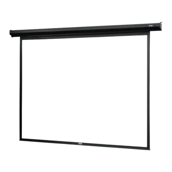
- Page 1 POWER PRESENTATION PRODUCTS Instruction Book for DA-LITE SCREEN COMPANY, INC. 3100 North Detroit Street Post Office Box 137 DESIGNER CONTOUR ELECTROL Warsaw, Indiana 46581-0137 Phone: 574/267-8101 800-622-3737 Fax: 574/267-7804 http:// www.da-lite.com e-mail: info@da-lite.com...
-
Page 2: Important Safety Instructions
IMPORTANT SAFETY INSTRUCTIONS When using your video equipment, basic safety precautions should always be followed, including the following: 1. Read and understand all instructions before using. 2. Position the cord so that it will not be tripped over, pulled, or contact hot surfaces. 3. -
Page 3: Installation
INSTALLATION Carefully unpack screen and remove outer wrapping from case. Remove the black tape from the slat bar after the case has been installed. There are three ways to install the Designer Contour CASE HOOK 4-1/4" Electrol: Wall Mount, Ceiling Mount, or Ceiling Hook. Procedures for each method are as follows: 5/16"... -
Page 4: Electrical Installation
ELECTRICAL INSTALLATION Internal wiring has been completed at the factory. Installer must route power to the wall switch and to the junction box located on the left end of the screen case. Standard installation is for a single 120VAC or 240VAC wall switch to control the screen. Optional Control units may have been ordered, including a low voltage control unit. -
Page 5: Screen Adjustment
SCREEN ADJUSTMENT Screen travel is stopped automatically in the down and up positions by the limit switches that are preset at the factory. If it’s necessary to adjust for more or less drop follow the steps below. Adjustment procedures are different for 120V and 240V units. - Page 6 SCREEN ADJUSTMENT INSTRUCTIONS FOR 240 VOLT SCREENS SETTING THE DOWN LIMIT POSITION TO REDUCE SCREEN DROP: Turn the limit switch screw counterclockwise to decrease the amount of screen drop. Run the screen down to test the stop position. If the screen drops too far, raise the screen about one foot and adjust the limit switch again. Repeat until the desired position is set.
-
Page 7: Troubleshooting
TROUBLESHOOTING SYMPTOM CAUSE SOLUTION 1. Screen will not operate. (a) Blown fuse. (a) Replace fuse. Motor does not hum. (b) Tripped circuit breaker. (b) Reset circuit breaker. (c) No power to operating switch (c) Check above. Tighten all loose or junction. wire connections. - Page 8 Printed in U.S.A. 89697 Rev. 1/04...
Need help?
Do you have a question about the DESIGNER CONTOUR ELECTROL and is the answer not in the manual?
Questions and answers