Advertisement
Quick Links
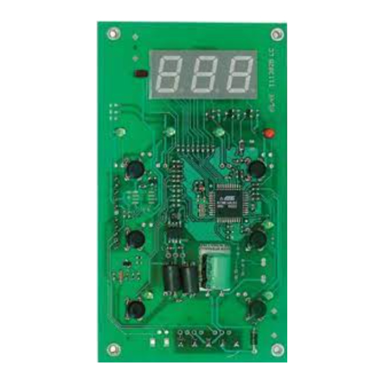
IWP 760 LX Fan Condenser
electronic controllers for "ventilated" refrigeration units
The device consists of two units:
• a standard 6-button "key" IWK keyboard
• an IWP power module.
USER INTERFACE
The user is supplied with a keyboard with
a display and four primary buttons + two
secondary buttons for controlling instru-
ment status and programming.
BUTTONS AND MENUS
"primary" buttons
UP Button
Scrolls through menu items, increases
values. Parameter programmable*
(see H31 parameter: by default
manual DEFROST is active)
DOWN button Scrolls through th
e menu items. Decreases values.
Parameter programmable*
(see H32 parameter)
esc button
ESC function (quit)
Parameter programmable*
(see H33 parameter)
**Activates functions
(see paragraph on
OSP FUNCTIONS FOLDER)
Set button
(press once)
MACHINE STATUS MENU
•Accesses set point
•Accesses RTC functions (if present)
•Displays alarms (if present)
•Displays Pb1,Pb2 and Pb3
(hold down)
PARAMETER PROGRAMMING MENU
•Accesses Programming menu
parameters
UP button +esc button pressed simultaneously
(press for 2 seconds)
•Locks/unlocks keyboard
"Secondary" or function buttons
"Fnc2" button
(hold down, see par.)
H02)
(Stand-by default)
Switches unit on/off
Parameter programmable*
(see H35 parameter)
"Fnc1" button
(light default)
Switches on light
Parameter programmable*
(see H34 parameter)
*NOTE :
a) The "primary" buttons can be pro-
grammed using parameters H31...H33 (see
parameter table).
In standard configuration the buttons are
set by default as:
• "UP" button; par. H31=1; activates manu-
al defrosting
• "DOWN" button; par. H32=0 no related
4 signal LEDs
+ 3 button
LEDs
"UP" button
"DOWN" button
"fnc2" button
"on-off" default
function (disabled)
• "esc" button; par. H33=0 does not acti-
vate any function.
• "set" button; not programmable.
b) The "secondary" or "function buttons"
can be programmed using parameters
H34...H35 (see).
In standard configuration the buttons are
set by default as:
• "UP" button; par. H34=6; activates light
• "DOWN" button; par. H35=7 activates
"ON-OFF" function (also called STAND-BY).
LEDS
"Display" LEDs
The display is red; the display LEDs (from left
to right) are green (3) and red (Alarm LED).
Compressor LED (green)
•ON when compressor is on;
•blinking for delay, protection
or enabling blocked
Defrost LED (green)
•ON when defrosting is in progress;
•blinking when activated manually
or with digital input
Fan LED (green)
•ON when fan is on;
•blinking for manual or D.I.
(Digital Input) fan forcing
Alarm LED (red)
•ON for active alarm;
•blinking for silenced alarm
3-figure display
"esc" button
"set" button
PRIMARY BUTTONS
"fnc1" button
light default
SECONDARY BUTTONS
"Button" LEDs
3 LEDs are associated with the set,
"on-off" and "LIGHT" buttons on the
keyboard provided.
"set" LED (yellow)
•ON for parameter programming level 2;
•blinking when reduced set point is entered OSP
"on-off" LED (yellow)
•ON when unit is "off" (on STAND-BY);
•OFF when unit is on;
"light" LED (green)
•ON when output is active, (%RH / light depending on
model and/or default settings);
ON when output is also active from D.I.
N.B.: the LEDS are OFF in all other circumstances
KEYBOARD LOCKED
Press the "UP" and "esc" buttons for 2 sec-
onds to lock the keyboard. Repeat to
unlock. The keyboard can also be locked
from a parameter (par. LOC).
The IWK keyboard can be disabled by pro-
gramming the "Loc" parameter (see "diS"
folder).
ACTIVATING MANUAL DEFROST CYCLE
To activate the defrost cycle manually,
press the "UP" button for H02 seconds (if
config. =1).
If the defrosting conditions are incorrect
(the temperature of the evaporator probe
is higher than the end of defrosting tem-
perature, for example) or parameter
OdO≠0, the display will flash three (3)
times to indicate that the operation will
not be performed.
Advertisement

Related Manuals for Eliwell IWP 760 LX


Summary of Contents for Eliwell IWP 760 LX
- Page 1 IWP 760 LX Fan Condenser electronic controllers for “ventilated” refrigeration units The device consists of two units: • a standard 6-button “key” IWK keyboard • an IWP power module. 4 signal LEDs + 3 button LEDs 3-figure display USER INTERFACE...
- Page 2 • UPLOAD: instrument —> Copy Card required value, access the “Keyboard Local • DOWNLOAD: Copy Card —> instr. Programming” menu in the “PLO” folder. If passwords are enabled, they will be requested: - PA3 when entering the “PLO” menu IWP 760 LX Fan Condenser 2/14...
- Page 3 2 par level 1 par level 2 par level 1 par level 1 par level 2 par level 2 par level 1 par level 2 scroll functions functions UP DOWN activate/disactivate function level 1 IWP 760 LX Fan Condenser 3/14...
-
Page 4: Advanced Functions
NOTE: technical information on control Storage temperature: -30…85 °C. - the label PA is displayed in the subfolder of the IWP 760 LX Fan Condenser using Usage ambient humidity: 10…90 % RH the Modbus protocol is available in the (non-condensing). - Page 5 This means, for example, that an error introduced by the probe is added to (LONG DISTANCE) Keyboard connection any error that is characteristic of the instru- Multiple Base board- VDD, +, - GND plug-in module ment. Keyboard connection optional IWP 760 LX Fan Condenser 5/14...
- Page 6 End of defrost temperature (determined by evapo- -50.0...150 °C/°F rator probe) NOTE: At level 1 the folders will only display all the level 1 parameters. At level 2 the folders will only display all the level 2 parameters. IWP 760 LX Fan Condenser 6/14...
- Page 7 Alarm exclusion time after defrosting 0...999 NOTE: At level 1 the folders will only display all the level 1 parameters. At level 2 the folders will only display all the level 2 parameters. IWP 760 LX Fan Condenser 7/14...
- Page 8 Delay in enabling fans with consensus 0...250 NOTE: At level 1 the folders will only display all the level 1 parameters. At level 2 the folders will only display all the level 2 parameters. IWP 760 LX Fan Condenser 8/14...
- Page 9 2 as specified by parameter CA NOTE: At level 1 the folders will only display all the level 1 parameters. At level 2 the folders will only display all the level 2 parameters. IWP 760 LX Fan Condenser 9/14...
- Page 10 12= condenser fans (see page 4/14 Condenser Fan Controller) NOTE: At level 1 the folders will only display all the level 1 parameters. At level 2 the folders will only display all the level 2 parameters. IWP 760 LX Fan Condenser 10/14...
- Page 11 Formatting. Cancels all data in the Copy Card NOTE: At level 1 the folders will only display all the level 1 parameters. At level 2 the folders will only display all the level 2 parameters. IWP 760 LX Fan Condenser 11/14...
- Page 12 Controls srl has taken all possible measures to guarantee the accuracy of this document, it declines any responsibility for any damage arising out of its use. The same applies to any person or company involved in preparing and writing this manual. Eliwell Controls srl reserves the right to make any changes or improvements with- out prior notice and at any time.
- Page 13 4 5 6 8 9 10 1 2 3 4 5 6 8 9 10 1 2 3 4 5 6 8 9 10 GND optional BASE BOARD IWP BASE BOARD IWP BASE BOARD IWP IWP 760 LX Fan Condenser 13/14...
- Page 14 IWP 760 LX BASE BOARD CONNECTIONS LONG SHORT DISTANCE DISTANCE TELEVIS D.I.1 D.I.2 D.I.3 D.I.4 1 2 3 4 5 6 8 9 10 11 12 13 14 15 16 17 18 19 20 21 22 23 24 25 Copy...
Need help?
Do you have a question about the IWP 760 LX and is the answer not in the manual?
Questions and answers