Table of Contents
Advertisement
Quick Links
ID 985/S/E/CK - ID985/E LX
electronic controllers for "ventilated" refrigeration units
w w
i i
t t
h h
R R
S S
4 4
8 8
5 5
o o
n n
b b
w w
i i
t t
h h
R R
S S
4 4
8 8
5 5
o o
n n
b b
UP button
Scrolls through the menu items
Increases values
Activates manual defrosting
(see H31 parameter)
DOWN button
Scrolls through the menu items
Decreases the values
Parameter programmable
(see H32 parameter)
MACHINE STATUS MENU DIAGRAM
set
press and release
(single press)
Position
Associated function
Set point/Reduced set point ON for parameter programming level 2
Compressor or relay 1
Defrosting
Alarm
Fans
aux
aux
o o
a a
r r
d d
( (
I I
D D
9 9
8 8
5 5
/ /
S S
/ /
E E
/ /
C C
o o
a a
r r
d d
( (
I I
D D
9 9
8 8
5 5
/ /
S S
/ /
E E
/ /
C C
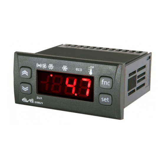
BUTTONS AND DISPLAY
ID985/E LX
set
alarms
AL
show alarms
set
SEt value
SEt
change SEt
value
d00
set
rtc
h00
'00
set
Pb1 value
Pb1
set
Pb2 value
Pb2
set
Pb3 value
Pb3
LEDS
Status
blinking when reduced set point is entered
(set point ON for setting set point)
ON for compressor on; blinking
for protection delay or enabling blocked
ON when defrosting in progress; blinking when activated
manually or by digital input
ON for active alarm; blinking for silenced alarm
ON when fan is on
ON when auxiliary output is operating
K K
) )
a a
n n
d d
r r
e e
m m
o o
t t
e e
d d
K K
) )
a a
n n
d d
r r
e e
m m
o o
t t
e e
d d
fnc
set
aux
if alarm(s)
present
d00= Sunday
set
days
2 sec
set
hours
2 sec
set
minutes
se presente
if present
if present
i i
s s
p p
l l
a a
y y
i i
s s
p p
l l
a a
y y
fnc button
ESC function (quit)
fnc
Parameter programmable
(see H33 parameter
Set button
Accesses Set point and rtc folder
set
Accesses the Menus
Confirms the commands
Displays the alarms (if active)
Stores hours/min
USER INTERFACE
The user has a display and four buttons
for controlling instrument status and pro-
gramming. The device can also be con-
nected to a remote display.
At start-up the instrument performs a
Lamp Test; the display and LEDs flash for a
few seconds to check that they are work-
ing correctly. The instrument has two main
menus: the Machine Status menu and the
Programming menu.
ACCESSING AND USING MENUS
The resources are arranged in a menu that
can be accessed by pressing and quickly
releasing the "set" button (Machine Status
menu) or holding down the "set" button
for more than 5 seconds (Programming
menu). To access the contents of each
folder indicated by the relevant label, just
press the "set" button once.
You can now scroll through the contents
of each folder, modify it or use its func-
tions.
If you do not use the keyboard for over 15
seconds (time-out) or if you press the
"fnc" button once, the last value shown on
the display is confirmed and you are taken
back to the previous screen mask.
REMOTE DISPLAY
This has a display with 3 digits + sign that
displays the parameter programming and
alarm display values on the controller it is
connected to during probe reading.
MACHINE STATUS MENU
(See Machine Status Menu Diagram)
Advertisement
Table of Contents

Related Manuals for Eliwell ID 985


Summary of Contents for Eliwell ID 985
- Page 1 ID 985/S/E/CK - ID985/E LX electronic controllers for “ventilated” refrigeration units BUTTONS AND DISPLAY UP button fnc button Scrolls through the menu items ESC function (quit) Increases values Parameter programmable Activates manual defrosting (see H33 parameter (see H31 parameter) Set button...
- Page 2 At each level in both menus, when the “fnc” button is pressed or the 15 second time out elapses, you are taken back to the higher display level and the last value on the display is stored. ID 985/S/E/CK - ID985/E LX 2/14...
-
Page 3: Advanced Functions
Reduced set point SP** modes are defined: The functions are associated with the instruments by correctly setting the para- Pressure switch alarm reset meters (see the parameter table for the **default “Lin” label folder) ID 985/S/E/CK - ID985/E LX 3/14... - Page 4 The error condition for probe 3 (display) occurs. Dripping starts when both defrosts counts are disabled. causes the following: have been completed. • E3 code appears on display Other alarms do not appear on the instrument display ID 985/S/E/CK - ID985/E LX 4/14...
-
Page 5: Electrical Connections
ID 985/S/E/CK - ID985/E LX 5/14... - Page 6 NOTE: At level 1 the folders will only display all the level 1 parameters. At level 2 the folders will only display all the level 2 parameters. The level marked 1-2 allows the parameter to be displayed at both levels. 6/14 ID 985/S/E/CK - ID985/E LX...
- Page 7 NOTE: At level 1 the folders will only display all the level 1 parameters. At level 2 the folders will only display all the level 2 parameters. The level marked 1-2 allows the parameter to be displayed at both levels. ID 985/S/E/CK - ID985/E LX 7/14...
- Page 8 NOTE: At level 1 the folders will only display all the level 1 parameters. At level 2 the folders will only display all the level 2 parameters. The level marked 1-2 allows the parameter to be displayed at both levels. ID 985/S/E/CK - ID985/E LX 8/14...
- Page 9 NOTE: At level 1 the folders will only display all the level 1 parameters. At level 2 the folders will only display all the level 2 parameters. The level marked 1-2 allows the parameter to be displayed at both levels. ID 985/S/E/CK - ID985/E LX 9/14...
- Page 10 NOTE: At level 1 the folders will only display all the level 1 parameters. At level 2 the folders will only display all the level 2 parameters. The level marked 1-2 allows the parameter to be displayed at both levels. ID 985/S/E/CK - ID985/E LX 10/14...
- Page 11 (9) Only for Modbus models * Value: to be compiled manually by user with any custom settings (if different from default settings) ** Level: indicates the visibility level of parameters accessed using a password (see relevant paragraph) ID 985/S/E/CK - ID985/E LX 11/14...
-
Page 12: Responsibility And Residual Risks
Televis or ModBUS supervision system. PCInterface1110/1120 RS-232/RS-485 serial interface for connecting a PC and a series of instruments in an RS-485 network. The device needs the BlueCard activation module supplied with the Eliwell software package licence to be plugged in. Personal Computer Personal Computer... - Page 13 TECHNICAL DATA ID 985/S/E/CK - ID 985/E LX - ECHO IP65. Front protection PC+ABS UL94 V-0 resin plastic body, polycarbonate front, thermoplastic resin buttons. Casing front 74x32 mm, 60 mm depth. Dimensions ID985/S/E/CK - ID985/E LX front 48x28.6 mm, 15 mm depth.
- Page 14 Sales +39 0437 986 100 (Italy) • +39 0437 986 200 (other countries) • E-mail saleseliwell@invensyscontrols.com Technical helpline +39 0437 986 300 • E-mail techsuppeliwell@invensyscontrols.com www.eliwell.it © Eliwell Controls s.r.l. 2008 All rights reserved. code. 9IS23080 - GB - rel. 4/08...
Need help?
Do you have a question about the ID 985 and is the answer not in the manual?
Questions and answers
220 saplai kisme de