Table of Contents
Advertisement
cod. 9IS43080
GB
rel. 3/05
USER INTERFACE
The user has a display and four buttons
for controlling instrument status and pro-
gramming. The device can also be con-
nected to a remote display.
At start-up the instrument performs a
Lamp Test; the display and LEDs flash for a
few seconds to check that they are work-
ing correctly. The instrument has two main
menus: the Machine Status menu and the
Programming menu.
ACCESSING AND USING MENUS
The resources are arranged in a menu that
can be accessed by pressing and quickly
releasing the "set" button (Machine Status
menu) or holding down the "set" button
for more than 5 seconds (Programming
menu). To access the contents of each
UP button
Scrolls through the menu items
Increases values
Activates manual defrosting
(see H31 parameter)
DOWN button
Scrolls through the menu items
Decreases the values
Parameter programmable
(see H32 parameter)
Position
Associated function
Set point/Reduced set point ON for parameter programming level 2
Compressor or relay 1
Defrosting
Alarm
Fans
aux
aux
ID 985 /E LX
electronic controllers for "ventilated" refrigeration
units with remote display
folder indicated by the relevant label, just
press the "set" button once.
You can now scroll through the contents
of each folder, modify it or use its func-
tions.
If you do not use the keyboard for over 15
seconds (time-out) or if you press the
"fnc" button once, the last value shown on
the display is confirmed and you are taken
back to the previous screen mask.
REMOTE DISPLAY
This has a display with 3 digits + sign that
displays the parameter programming and
alarm display values on the controller it is
connected to during probe reading.
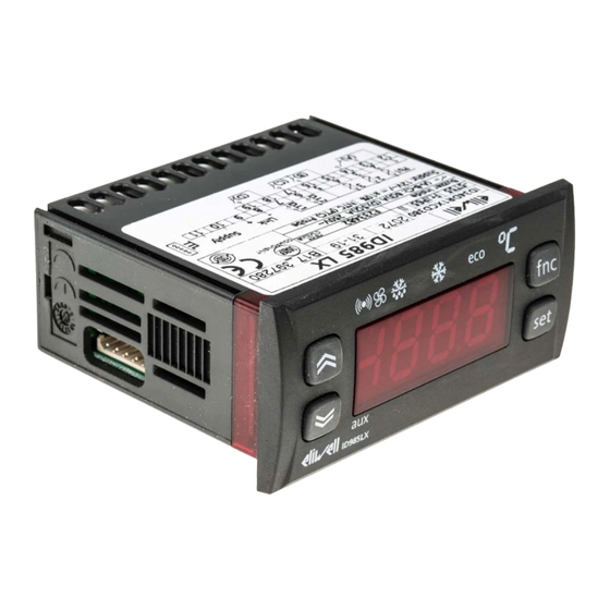
BUTTONS AND DISPLAY
aux
ID985/E LX
LEDs
Status
blinking when reduced set point is entered
(set point ON for setting set point)
ON for compressor on; blinking
for protection delay or enabling blocked
ON when defrosting in progress; blinking when activated
manually or by digital input
ON for active alarm; blinking for silenced alarm
ON when fan is on
ON when auxiliary output is operating
MACHINE STATUS MENU
(See Machine Status Menu Diagram)
To access the Machine Status menu, press
the "set" button and quickly release it.
If no alarms are present, the label "SEt"
appears. By using the "UP" and "DOWN"
buttons you can scroll through the other
folders in the menu:
-AL: alarm folder (if alarms present, except
for faulty probes/probe errors;
-SEt: Set point setting folder.
-rtc: Real Time Clock folder
-Pb1: probe 1 value folder;
-Pb2: probe 2 value folder;
-Pb3: probe 3 value folder (if present);
fnc button
ESC function (quit)
fnc
Parameter programmable
(see H33 parameter
fnc
set
Set button
Accesses Set point and rtc folder
set
Accesses the Menus
Confirms the commands
Displays the alarms (if active)
Stores hours/min
Set setting
Access the "Machine Status" menu, press
the "set" button and quickly release it. The
"Set" folder label appears. To display the
Set point value, press the "set" button
again.
The Set point value appears on the display.
To change the Set point value, use the
"UP" and "DOWN" buttons within 15 sec-
onds. If the parameter is LOC = y the Set
point cannot be changed.
Alarm on
If an alarm condition exists when the
Machine Status menu is accessed the "AL"
folder label appears (see section on
"Diagnostics").
Real Time Clock
By pressing the "set" button when the
"rtc" label appears, the label d00 (days) is
Advertisement
Table of Contents

Related Manuals for Eliwell ID 985 E


Summary of Contents for Eliwell ID 985 E
- Page 1 ID 985 /E LX electronic controllers for “ventilated” refrigeration cod. 9IS43080 units with remote display rel. 3/05 USER INTERFACE folder indicated by the relevant label, just MACHINE STATUS MENU press the “set” button once. (See Machine Status Menu Diagram) The user has a display and four buttons for controlling instrument status and pro- You can now scroll through the contents To access the Machine Status menu, press...
-
Page 2: Advanced Functions
displayed. Use the “UP” and “DOWN” but- with the “set” button. Move on to the next UL-Upload tons to set days. If you do not use the but- parameter. This operation uploads the programming tons for over 2 seconds or if you press NOTE: We strongly recommend that you parameters from the instrument. - Page 3 Description Master a) configure the 3 probe in 2nd evapora- Digital input switches off loads D.I. activation delay Instrument that controls the networks and tor defrost control mode (par. H43=2EP). Alarm signal delay after disabling the digi- sends commands to the Slaves. The Master b) configure a relay output as 2nd evapo- tal input (door closed) is selected using parameter L00 (the value 0...
- Page 4 GENERAL PRESSURE SWITCH INPUT Probe 3 can be excluded and the failed This type of alarm does not affect the reg- CONTROLLER connection with the instrument will not ulating in progress. trigger an error message. Alarms are considered as absolute This controller performs diagnostics on an NOTE: During dripping time the output is (default) values or as values related to the...
-
Page 5: Electrical Connections
ELECTRICAL 4 outputs on relays: first output (A) SPDT NOTE: Do not set parameter tAo to 8(3)A 250Va, second and third output (B- CONNECTIONS zero when the door is closed since if C) SPST 8(3)A 250Va, fourth output (D) the door is continually opened and SPST 5(2)A 250Va. - Page 6 RANGE DEFAULT VALUE LEVEL U.M. PAR. DESCRIPTION Set point with range falling between the minimum LSE...HSE °C/°F LSE set point and the maximum HSE set point. The value of the set point is in the machine status menu The compressor stops when it reaches the set 0.1...30.0 °C/°F point value, and restarts at a value corresponding...
- Page 7 RANGE DEFAULT VALUE* LEVEL** U.M. PAR. DESCRIPTION Determines when instrument starts up if the flag defrosting cycle must be activated (if the tempera- ture on the evaporator allows this) y=defrosting activated at start-up n=defrosting not activated at start-up Minimum time for each compressor state before -31...31 defrosting “Ontime if >0;...
- Page 8 RANGE DEFAULT VALUE* LEVEL** U.M. PAR. DESCRIPTION Determines if “LAL” and “HAL” are expressed as flag absolute values or as a differential related to the set point 0=absolute value 1=value related to set point Alarm differential 1.0...50.0 °C/°F HAL (4) Maximum alarm.
- Page 9 PAR. DESCRIPTION RANGE DEFAULT VALUE* LEVEL** U.M. Selects the instrument as Master 0...7 (0), Slave (from 1 to 7). Number of Slaves in the Network Refers to Master 0...7 only Number of Slaves in network (from 0 to 7). Per Slaves/Echo leave value =0 Enables ECHO control on slave: 0=instrument does not control ECHO 1=instrument controls ECHO...
- Page 10 RANGE DEFAULT VALUE* LEVEL** U.M. PAR. DESCRIPTION Minimum value that can be displayed -55.0...302 °C/°F -50.0 Maximum value that can be displayed -55.0...302 °C/°F 140.0 Display during defrosting: 0/1/2 flag 0= displays temperature read by thermostat con- trol probe 1= displays temperature read entering defrost cycle until set point is reached 2= displays “deF”...
- Page 11 RANGE DEFAULT VALUE* LEVEL** U.M. PAR. DESCRIPTION Digital output 4 configurability Same as H21 0...10 (default alarm) H25 (7) BUZZER output configurability 0...10 0= disabled 1...7= not used 8=enabled (default) if buzzer is present UP button configurability 0...8 0=disabled 1=defrost 2=auxiliary 3=reduced set point 4=HACCP alarm reset...
- Page 12 Duty Cycle Diagram The error condition for probe 1 (compressor) causes the follow- Ont, OFt parameters programmed for ing: Duty Cycle • E1 code appears on display • the controller is activated as Compressor output indicated by the “Ont” and “OFt”...
-
Page 13: Responsibility And Residual Risks
TTL input for Copy Card and connection to Televis RESPONSIBILITY AND DISCLAIMER RESIDUAL RISKS Eliwell & Controlli S.r.L. shall not be liable for any dam- This document is the exclusive property of Eliwell & Eliwell & Controlli s.r.l. ages deriving from: Controlli S.r.L.
Need help?
Do you have a question about the ID 985 E and is the answer not in the manual?
Questions and answers