Table of Contents
Advertisement
Quick Links
COD. 9IS23033
I
REL. 3/04
The device consists of two units:
• a IWK keyboard available in 3 sizes
(see below and in paragraph on
Models)*;
• an IWP power module.
The IWK keyboard is connected to the
IWP power module using an "powered"
serial connection also referred to as
SHORT DISTANCE.
*Different types of IWK keyboards are
available: the functions and connec-
tion of the standard 32x74 4 button
IWK keyboard are illustrated below.
For information on this and other key-
boards, refer to the relevant technical
data sheets.
MODELS
Model
Characteristics
IWK keyboard
IWK std 6 buttons
open board keyboard
68x124mm (LxH)
IWK 32x74 4
Eliwell std. keyboard
buttons
32x74x60mm (LxHxD)
IWK wide
"IWC" style keyboard
6 (max 8) buttons
180x37x45mm (LxHxD)
IWP power module
IWP 740 (LX)
base module with 4 relays
92x121mm (LxH)
PLEASE NOTE - IF WIDE OR "OPEN"
KEYBOARDS ARE USED, SOME FUNC-
TIONS RELATED TO THE DEDICATED
BUTTONS MAY NOT BE AVAILABLE:
READ THE USER INTERFACE SECTION
ONLY FOR IWK WIDE AND 6-BUTTON
KEYBOARDS
" AND TABLE OF PARAMETERS, "config-
uration parameters"
PLEASE NOTE - WIDE AND 32X74 KEY-
BOARD ALL LEDS ARE RED
IWP 740 (LX)
Electronic controllers for "ventilated" refrigerating units
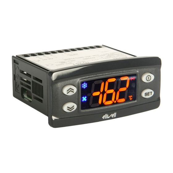
USER INTERFACE
eco
aux
IWK
(example of a standard 32x74 4-button
keyboard).
The user has a keyboard with a 6 LED
display and four buttons for controlling
status and programming of the instru-
ment.
BUTTONS AND MENUS
UP Button
Scrolls through the menu items
Increases the values
Parameter programmable*
(see H31 parameter: by default
Manual DEFROST is defrost)
DOWN Button
Scrolls through the menu items
Decreases the values
Parameter programmable*
(see parameter H32, by default
aux relay is active)
ESC button
ESC function (exit)
fnc
Parameter programmable*
(see H33 parameter)
set button
(press once)
set
MACHINE STATUS MENU
•Accesses the set point
•Displays the alarms
(if active)
•Dispays Pb1,Pb2 and Pb3
(see)
(hold down)
•Accesses the programming
Menu Parameters
UP button +esc button pressed simultaneously
(press for 2 seconds)
fnc
•Keyboard locking/unlocking
FOR WIDE AND 6 BUTTON IWK KEYBOARDS
"secondary" or function buttons
"ON-OFF"
(hold down, see par.H02)
(function 2)
Switches unit on/off
Parameter programmable*
(see H35 parameter)
"LIGHT" button
(function 1)
Switches on the light
Parameter programmable*
(see H34 parameter)
*NOTE:
The "primary" buttons can be pro-
grammed using the parameters H31...H33
(see)
f nc
In standard configuration the buttons are
set by default as:
• "UP" button; par. H31=1; enables
set
manual defrosting
• "DOWN" button; par. H32=0 no related
function (disabled)
• "esc" button; par. H33=3 enables the
reduced set function
• "set" button; not programmable.
LEDS
"Display" LEDs
The display is red, the 6 LEDs are red
"eco" LED
•ON for parameter programming level 2;
•blinking when OSP reduced set is entered
Compressor LED
ON for compressor on;
•blinking for protection delay, or enabling
blocked.
Defrosting LED
ON when automatic defrosting in progress;
•blinking when manual defrosting is in
progress;
LED Fans
•ON when fan is on;
•blinking for manual or D.I. (Digital Input)
fan forcing
(%RH function, humidity reduction
if par. H11=13)
Alarms LED
•ON for active alarm;
•blinking for silenced alarm
FOR IWK WIDE AND 6-BUTTON LED
KEYBOARDS ONLY
"set" LED
•ON for paramter programming level 2;
•blinking when OSPreduced set is entered
set
"on-off" LED
ON when unit "off" (on STAND-BY);
•OFF when unit on;
"light" LED
ON when output is active, (%RH / light
depending on model and/or default set-
tings);
ON when output is also active from D.I.
Advertisement
Table of Contents

Related Manuals for Eliwell IWP 740


Summary of Contents for Eliwell IWP 740
- Page 1 IWP 740 (LX) Electronic controllers for “ventilated” refrigerating units COD. 9IS23033 REL. 3/04 *NOTE: USER INTERFACE The device consists of two units: The “primary” buttons can be pro- • a IWK keyboard available in 3 sizes grammed using the parameters H31…H33...
- Page 2 -SEt: Setpoint setting folder; Programming Menu, and scroll down the The passwords “PA1” and “PA2” allow -rtc: real time clock folder; parameters until you reach the PA2 label. level 1 and level 2 parameters to be IWP 740 (LX) 2/20...
- Page 3 Master (with parameters L00..L09). E7), the Slaves will activate defrosting NOTE: The Slave Base according to parameter and functions associated with the events • after downloading the instrument will L08 is also enabled for: requested by the Slaves. IWP 740 (LX) 3/20...
- Page 4 3 (display) dripping cycle they will be turned off reset using the rAP (pressure switch causes the following: even if RH% is active. alarm reset) in the Fnc functions menu • E3 code appears on display. Other IWP 740 (LX) 4/20...
- Page 5 “AL” folder with the label The unit has been designed for: “EA”. The relay can be silenced; even if • 32x74 4 button IWK keyboard: panel the alarm icon starts blinking, controls mounted. Drill a 29x71 mm hole, insert IWP 740 (LX) 5/20...
- Page 6 2,5 Casing: open board. Dimensions: supplies contact the Sales Office). (only one conductor per terminal for •IWP 740 (LX) model 92x121 mm. power connections) for terminal capacity, Usage temperature: -5…55 °C. Storage see the label on the instrument.
- Page 7 Power supply: from IWP power module. Table of IWP Serial Outputs (see also network connections) Type Usage Lines Accessories (on IWP base) Serial in tension single Base Board- GND, DATA (SHORT DISTANCE) Keyboard 12V not connection Multiple connected Base-Keyboard connection IWP 740 (LX) 7/20...
- Page 8 Compressor off (before defrost). Time for compressor OFF before defrost cycle. If a 0…60 defrost cycle is set within the programmed time for this parameter, the compressor is not started up. If =0 function is stopped. IWP 740 (LX) 8/20...
- Page 9 0 = electrical defrosting; 3= With RTC. ON in dd and Fd 1 = cycle reversing defrosting (hot gas); OFF when Pb2=dSt or for time (dEt) 2 = Free mode defrosting. ON if requested from set point IWP 740 (LX) 9/20...
- Page 10 NOT performed and the set point values, differentials, etc. are NOT modified. All the temperature values set will therefore need reviewing. e.g. with a set point set to 10°C, when changing the value to °F the set point will become 10°G=F and not 50°F (according to the conversion table) IWP 740 (LX) 10/20...
- Page 11 This operation cannot be undone. label PA2 Inside the CnF folder you can access all level 2 parameters from label PA2 by pressing the “set” button. SEE paragraph 2) Displaying level 2 parameters IWP 740 (LX) 11/20...
- Page 12 * DEFAULT column: The term default identifies the standard factory-set configuration; (!) WARNING! It is strongly recommended that the unit is switched off and on again each time parameter configuration is changed in order to prevent malfunctioning of the configura- tion and/or ongoing timings. IWP 740 (LX) 12/20...
- Page 13 24.00* hours/min Time6 00-24, 00-59 24.00* hours/min Time6 00-24, 00-59 24.00* hours/min Tilme7 00-24, 00-59 Tilme7 hours/min 24.00* hours/min 00-24, 00-59 24.00* Time8 00-24, 00-59 24.00* hours/min Time8 00-24, 00-59 24.00* hours/min * 24=disabled * 24=disabled IWP 740 (LX) 13/20...
- Page 14 Event Duration Duration of 1st event. Sets the duration of the event. 0…99 hours Daily or Festive Defrost Block flag Blocking/unblocking daily or festive defrosting. NOTE: does not affect defrosting at intervals like Every Day event IWP 740 (LX) 14/20...
- Page 15 NOT USED nad (night and day) DIAGRAM press and release (single press) day 1 = sunday as above change value E00…03 day 2 = monday as above day 3 = tuesday as above Every Day IWP 740 (LX) 15/20...
- Page 16 (compressor) causes the follow- ing: • E1 code appears on display • the regulator is activated as Compressor output indicated by the “Ont” and >0 “OFt” parameters if pro- >0 grammed for the duty cycle >0 >0 IWP 740 (LX) 16/20...
- Page 17 (single press) present show alarms SEt value change SEt value d00= Sunday days 2 sec hours 2 sec minutes if present Pb1 value Pb2 value if present Pb3 value if present Machine Status Menu Diagram IWP 740 (LX) 17/20...
- Page 18 2 par level 1 par level 2 par level 2 par level 1 par level 1 par level 2 par level 1 level 2 par level 2 par level 2 par level 2 Programming Menu Diagram IWP 740 (LX) 18/20...
- Page 19 THE LINK NETWORK. FOR THIS REASON FIRST THE MASTER AND SLAVES BE CONFIGURED (WITH KEYBOARDS) AND THEN CONNECTED IN THE LINK NETWORK. 2 - FLICKERING OF THE DISPLAYS ON THE KEYBOARDS INDICATES THAT THE CONNECTED UNITS ALL HAVE THE SAME ADDRESS: DISCON- NECT THE LINK NETWORK AND PROGRAM EACH UNIT AS DESCRIBED ABOVE. IWP 740 (LX) 19/20...
- Page 20 DISCLAIMER Via dell'Industria, 15 Zona Industriale Paludi This document is exclusive property of Eliwell & Eliwell & Controlli srl shall not be liable for any 32010 Pieve d'Alpago (BL) ITALY Controlli srl and cannot be reproduced and circulated damages deriving from: unless expressly authorized by Eliwell &...
Need help?
Do you have a question about the IWP 740 and is the answer not in the manual?
Questions and answers