Table of Contents
Advertisement
cod. 9IS23071
GB
rel. 12/04
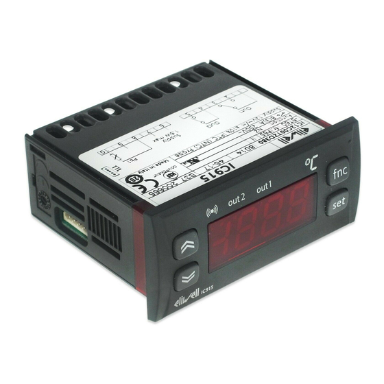
USER INTERFACE
The user has a display and four buttons
for controlling instrument status and pro-
gramming.
out 2
out 1
IC915LX
Scrolls through the menu items UP button
Increases the values
Parameter programmable
(par. H31)
Scrolls through the menu items
Decreases the values
Parameter programmable
(par. H32)
BUTTONS AND MENUS ACCESSING
AND USING MENUS
The resources are arranged in a menu that
can be accessed by pressing and quickly
releasing the "set" button (Machine Status
menu) or holding down the "set" button
for more than 5 seconds (Programming
menu).
To access the contents of each folder indi-
cated by the relevant label, just press the
"set" button once.
You can now scroll through the contents
of each folder, modify it or use its func-
tions. If you do not use the keyboard for
over 15 seconds (time-out) or if you press
the "fnc" button once, the last value
shown on the display is confirmed and you
are taken back to the previous screen
mask.
MACHINE STATUS MENU
(See Machine Status Menu Diagram)
To access the Machine Status menu, press
the "set" button and quickly release it.
The "SP1" label appears.
(If alarms are active, with the exception of
faulty probes/probe errors, the "AL" label
appears).
By using the "UP" and "DOWN" buttons
you can scroll through the other folders in
the menu: the folders are indicated below
in the order they appear:
-SP1: Set point 1 setting folder or
-AL: alarm folder (if alarms present, with
exception of faulty probes/probe errors);
-SP2: Set point 2 setting folder.
IC 915 (LX)
electronic controller with 2 set points and differential set point
adjustment
f nc
set
DOWN button
-Pb1: probe 1 value folder;
-Pb2: probe 2 value folder;
The folders are present according to
the presence and configuration of the
associated resource.
press and release
(quickly/single press)
out2
Alarm
out2
•ON for active
Relay 2 (OUT2)
alarm;
ON for relay on
•blinking when
(energized);blin
a silenced alarm
king for protec-
is still present
tion delay or
enabling
blocked
Set point button
MACHINE STATUS MENU DIAGRAM
set
AL
SP1
SP2
Pb1
Pb2
LEDs
out1
out1
ON when Set
Relay 1 (OUT1)
point is being
ON for relay on
set
(energized);blin
(and Set point
king for protec-
setting)
tion delay or
blinking when
enabling
Soft Start func-
blocked
tion is on
Soft Start
Set-point/
fnc button
ESC function (quit)
Parameter programmable
(par. H33)
fnc
1-Accesses Machine Status Menu
(SET POINTS, ACTIVE ALARMS,
PROBE READING) and labels/values;
set
1-Accesses Programming Menu
(PARAMETERS, COPY C ARD) and
relative labels/values;
3-Confirms commands
Alarm on
If an alarm condition exists when the
Machine Status menu is accessed, the "AL"
folder label appears (see "Diagnostics"
section).
set
alarms
show alarms
set
value SP1
change
SP1(2) value
set
value SP2
is present
set
value Pb1
set
value Pb2
is present
Reduced set
point
•ON to modify
Set-Point;
•blinking when
reduced set
point is entered
if alarm(s)
present
Advertisement
Table of Contents

Related Manuals for Eliwell IC 915


Summary of Contents for Eliwell IC 915
- Page 1 IC 915 (LX) cod. 9IS23071 electronic controller with 2 set points and differential set point rel. 12/04 adjustment USER INTERFACE LEDs The user has a display and four buttons out2 out1 for controlling instrument status and pro- Alarm out2 out1...
- Page 2 This operation downloads the program- • label DLn if operation fails ming parameters to the instrument. PLEASE NOTE: • after downloading the instrument will work with the parameter map settings that have just been downloaded. IC 915 LX 2/10...
- Page 3 2 par level 1 par parameters change level 2 par par value level 1 par level 2 par level 1 par level 2 par level 1 par scroll functions functions activate/disactivate function level 2 level 1 IC 915 LX 3/10...
- Page 4 PC and a series of instru- ments in an RS-485 network. The BusAdapter device needs the BlueCard activation module supplied with the Eliwell soft- ware package licence to be plugged in. RS485 The Televis remote control systems can be connected using the TTL serial port (the TTL- RS 485 BUS ADAPTER 130 or 150 interface module must be used).
- Page 5 H* maximum set point controller with differential dF1 negative C** minimum set point controller with differential dF2 positive NOTE: •for 1 and 2 examples with HC1=H e HC2=C; •for 3 HC1 and HC2 settings are ignored IC 915 LX 5/10...
- Page 6 -|LA1(2)|+AFd Maximum temperature alarm Temperature lower than or equal to HA1(2)-AFd Temperature lower than or equal to set point+HAL-AFd back swing if Att=reL(ative) LA1(2) must be negative: therefore set point+LAL<set point because set point+(-|LA1(2)|)=set-|LA1(2)| IC 915 LX 6/10...
- Page 7 PERIODIC CYCLE (folder with “cLc” label) Output ON time. 0…250 Output OFF time. 0…250 ***NOTE: At level 1 the folders will only display all the level 1 parameters. At level 2 the folders will only display all the level 2 parameters. IC 915 LX 7/10...
- Page 8 ***NOTE: At level 1 the folders will only display all the level 1 parameters. At level 2 the folders will only display all the level 2 parameters. IC 915 LX 8/10...
- Page 9 10°F and not 50°F when changing the value to °F (according to conversion table) ***NOTE: At level 1 the folders will only display all the level 1 parameters. At level 2 the folders will only display all the level 2 parameters. IC 915 LX 9/10...
- Page 10 DISCLAIMER RESPONSIBILITY AND RESIDUAL RISKS • as a 1 B type operated control device as regards its Eliwell & Controlli s.r.l. shall not be liable for any dam- This document is the exclusive property of Eliwell & automatic operating features;...
Need help?
Do you have a question about the IC 915 and is the answer not in the manual?
Questions and answers