Table of Contents
Advertisement
Your new tool has been engineered and manufactured to WEN's highest standards for dependability,
ease of operation, and operator safety. When properly cared for, this product will supply you years
of rugged, trouble-free performance. Pay close attention to the rules for safe operation, warnings,
and cautions. If you use your tool properly and for intended purpose, you will enjoy years of safe,
reliable service.
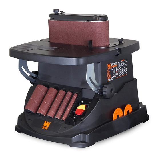
OSCILLATING BELT &
SPINDLE SANDER
IMPORTANT:
NEED HELP? CONTACT US!
Have product questions? Need technical support?
Please feel free to contact us at:
800-232-1195
techsupport@wenproducts.com
WENPRODUCTS.COM
Model # 6524
bit.ly/wenvideo
(M-F 8AM-5PM CST)
Advertisement
Table of Contents

Related Manuals for Wen 6524


Summary of Contents for Wen 6524
- Page 1 IMPORTANT: Your new tool has been engineered and manufactured to WEN’s highest standards for dependability, ease of operation, and operator safety. When properly cared for, this product will supply you years of rugged, trouble-free performance. Pay close attention to the rules for safe operation, warnings, and cautions.
- Page 2 Know Your Sander Assembly Operation Maintenance Troubleshooting Exploded View and Parts List Warranty TECHNICAL DATA Model Number: 6524 120 V, 60 Hz, 3.5A, 1/2 HP, 11,500 RPM Motor: 1575 FPM Belt Speed: 2000 RPM Spindle Speed: Oscillations: 58 OPM 5/8 in.
-
Page 3: General Safety Rules
GENERAL SAFETY RULES Safety is a combination of common sense, staying alert and knowing how your item works. SAVE THESE SAFE- TY INSTRUCTIONS. WARNING: To avoid mistakes and serious injury, do not plug in your tool until the following steps have been read and understood. - Page 4 GENERAL SAFETY RULES 15. DO NOT OVERREACH. Keep proper footing and balance at all times. Wear oil-resistant rubber-soled foot- wear. Keep the floor clear of oil, scrap, and other debris. 16. MAINTAIN TOOLS PROPERLY. ALWAYS keep tools clean and in good working order. Follow instruc- tions for lubricating and changing accessories.
-
Page 5: Electrical Information
SPECIFIC RULES FOR THE BELT & SPINDLE SANDER 10. Replace worn or damaged belts before operation. Always unplug the unit before making adjustments or chang- ing sandpaper or drums. 11. When sanding a large workpiece, provide additional support. Do not sand with the workpiece unsupported. 12. - Page 6 ELECTRICAL INFORMATION WARNING: This tool is for indoor use only. Do not expose to rain or use in damp locations. GUIDELINES FOR EXTENSION CORDS Make sure your extension cord is in good condition. When using an extension cord, be sure to use one heavy enough to carry the current your product will draw.
- Page 7 KNOW YOUR BELT & SPINDLE SANDER I - Table Insert A - Work Table J - Dust Port B - Sanding Belt K - Throat Plate Storage C - Belt Tracking Adjustment Knob L - Table Tilt Locking Knob D - Belt Tensioning Lever M - ON/OFF Switch E - Work Stop N - Sanding Drum Storage...
- Page 8 ASSEMBLY ASSEMBLY WARNING: To avoid injury from accidental startups, turn switch OFF and remove the plug from the power source outlet before making any adjustments. NOTE: The table insert is only to be used with the sanding drums, not with the sanding belt attachment. Place the spindle nut, table inserts, sanding drums, sanding sleeves, spindle washers, belt-sanding attachment and spindle nut wrench in the appropriate storage slots beneath the table (Fig.
- Page 9 OPERATION DUST COLLECTION (Fig. D) WARNING: This machine creates a lot of dust. Inhaling said dust on a regular basis can cause permanent respiratory illness. Minimize your exposure by wearing a respirator and using a dust col- lector. If you do not use some method of dust extraction or collection, the motor could overheat and fail.
-
Page 10: Spindle Sanding
OPERATION SPINDLE SANDING Spindle sanding is the preferred method of removing material from inside curves and irregular edges. The oscillat- ing spindle moves up and down as it rotates to help smooth surfaces more quickly and evenly than a non-oscillating sander. - Page 11 OPERATION CHANGING/REPLACING SANDING DRUMS AND SLEEVES 1. As always, disconnect the sander from the power source. 2. Remove the spindle sanding components in reverse order of the installation (Fig. F). 3. Clean all sawdust and debris from the opening for the table insert, the throat plates and any other areas where it may have collected.
- Page 12 OPERATION BELT SANDING OUTSIDE CURVES Belt Rotation 1. Turn sander ON and allow it to reach full Direction speed before applying a load. 2. Using both hands, slowly guide the workpiece against the sanding belt. Maintain downward pressure on the workpiece against the table, gently working it along the sanding belt until the desired curve has been created (Fig.
-
Page 13: Overload Protection
OPERATION ADJUST THE TRACKING OF THE SANDING BELT 1. Install the belt sanding attachment and remove all tools from the sander. 2. Connect the sander to a power source and turn it ON. Immediately turn the machine OFF, checking to see if the sanding belt rides centered on the drums, and does not move toward the top nor the bottom edge of the belt sanding attachment. - Page 14 MAINTENANCE WARNING: For your own safety, turn the switch OFF and remove the plug from the electrical outlet before adjusting or performing maintenance on the belt/spindle sander. Before using, check to make sure parts are not damaged, missing, or worn. Check for alignment of moving parts, binding of moving parts, improper mounting, or any other conditions that may affect the sander’s safe operation.
-
Page 15: Troubleshooting
TROUBLESHOOTING PROBLEM CAUSE SOLUTION Sanding grains 1) Sanding belt/sleeve has been stored in 1) Store sanding accessories away from ex- easily rub off the wrong environment. tremely hot/dry temperatures. 2) Sanding belt/sleeve has been damaged or 2) Store sanding accessories properly, without folded. - Page 16 EXPLODED VIEW AND PARTS LIST Part No. Description Part No. Description 6523-001 Hex Nut, M8 6523-034 Drum Housing Support 6523-002 Ball Bearing 6523-035 Square Nut, M6 6523-003 Aluminum Drum Wheel, 3” x 4” 6523-036 Dust Port Gasket 6523-004 Spindle Washer (3 pcs) 6523-037 Dust Port, 1-1/2”...
- Page 17 Bearing Sleeve, Lower 6523-127 Table Insert 6523-092 Metal Switch Plate 6523-128 Strain Relief 6523-093 Plastic Switch Plate Cover 6523-130 Power Cord 6524-094 Switch Pivot Plate Base 6523-131 Cord Clamp 6523-095 Switch Pivot Plate 6523-132 Throat Plate, 1-1/2” 6523-096 Switch 6523-133 Throat Plate, 2”...
- Page 18 EXPLODED VIEW AND PARTS LIST 125 126 127 136A...
- Page 19 LIMITED TWO YEAR WARRANTY WEN Products is committed to building tools that are dependable for years. Our warranties are consistent with this commitment and our dedication to quality. LIMITED WARRANTY OF WEN CONSUMER POWER TOOLS PRODUCTS FOR HOME USE GREAT LAKES TECHNOLOGIES, LLC (“Seller”) warrants to the original purchaser only, that all WEN con- sumer power tools will be free from defects in material or workmanship for a period of two (2) years from date of purchase.
- Page 20 THANKS FOR REMEMBERING...
Need help?
Do you have a question about the 6524 and is the answer not in the manual?
Questions and answers