Table of Contents
Advertisement
Available languages
Available languages
Quick Links
1
2
3
4
5
6
7
8
9
10
MGM T
CON SOLE
1
2
3
4
5
6
7
8
9
10
1
2
3
4
5
6
7
8
9
10
MGM T
CON SOLE
1
2
3
4
5
6
7
8
9
10
S5870 SERIES ETHERNET SWITCHES
ETHERNET-SWITCHES DER S5870 SERIE
SWITCHS ETHERNET DE LA SÉRIE S5870
S����シリーズイーサネットスイッチ
Quick Start Guide
Quick-Start Anleitung
Guide de Démarrage Rapide
クイックスタートガイド
STK M/S
RESE T
11
12
SYS
13
PSU1
14
STK1
15
FAN
16
PRI
17
PSU2
18
STK2
19
PoE
20
21
22
23
24
25
26
27
28
29
30
31
11
12
13
14
15
16
17
STK M/S
18
19
RESE T
20
11
21
12
22
SYS
23
13
14
PSU1
24
STK1
25
15
16
PRI
FAN
26
27
17
18
PSU2
28
STK2
29
19
20
PoE
30
31
21
32
22
23
24
25
26
27
28
29
30
31
32
11
12
13
14
15
16
17
18
19
20
21
22
23
24
25
26
27
28
29
30
31
32
V1.0
32
33
34
35
36
37
38
39
40
41
42
43
44
45
46
47
48
49
50
51
52
33
34
35
36
37
38
39
40
41
42
33
43
34
44
35
45
36
46
47
37
48
38
39
49
40
50
41
51
42
52
43
44
45
46
47
48
49
50
S587 0-48
51
52
33
34
35
36
37
38
39
40
41
42
43
44
45
46
47
48
49
50
51
52
53
S587 0-48
T6B C
53
54
53
54
T6B C-U PoE
+
53
54
54
Advertisement
Table of Contents

Related Manuals for FS S5870 Series


Summary of Contents for FS S5870 Series
- Page 1 RESE T PSU1 STK1 PSU2 STK2 MGM T CON SOLE S587 0-48 T6B C-U PoE S5870 SERIES ETHERNET SWITCHES ETHERNET-SWITCHES DER S5870 SERIE SWITCHS ETHERNET DE LA SÉRIE S5870 S����シリーズイーサネットスイッチ Quick Start Guide V1.0 Quick-Start Anleitung Guide de Démarrage Rapide クイックスタートガイド...
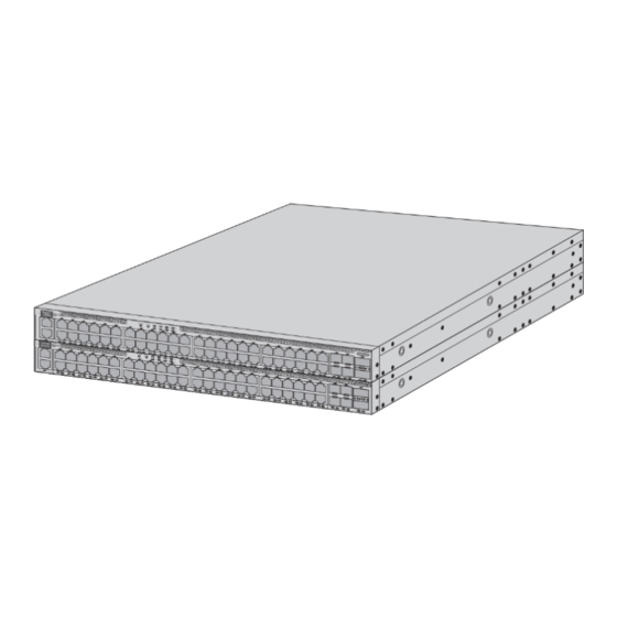
- Page 2 Introduction Thank you for choosing the S5870 Series Ethernet Switches. This guide is designed to familiarize you with the layout of the switches and describes how to mount them. STK M/S RESET PSU1 STK1 S5870-48T6BC-U PoE+ PSU2 STK2 S5870-48T6BC-U MGMT...
-
Page 3: Hardware Overview
An RJ45 console port for serial management A USB management port for software and con guration backup and o ine software upgrade NOTE: For information on LEDs and buttons, check the PicOS manual or FS documents online, or ask the technical support personnel for help. -
Page 4: Installation Requirements
Installation Requirements Before you begin the installation, make sure that you have the following: Phillips screwdriver. Screws and cage nuts for rack mounting. Grounding cable, screws, and washers for grounding the switch. ST K M /S RE SE M GM CO N SO LE SY S... -
Page 5: Mounting The Switch
Mounting the Switch Rack Mounting S5 87 0- 48 T6 BC 1. Secure the front- and rear-post brackets to the two sides of the switch with the supplied screws. ST K M/ S RE SE T SY S PS U1 ST K1 FA N PR I... -
Page 6: Grounding The Switch
ST K M /S RE SE T SY S PS U1 PR I PS U2 M GM T CO NS OL 3. Adjust the position of rear-post brackets and lock them with the bracket-locking screws. Grounding the Switch ST K M /S RE SE T SY S PS U1... - Page 7 Connecting the RJ45/RJ45 PoE Ports ST K M /S RE SE T SY S PS U1 ST K1 FA N PR I PS U2 ST K2 Po E M GM T CO NS OL S5 87 0- 48 T6 BC 1.
- Page 8 Connecting the QSFP28 Ports ST K1 FA N ST K2 Po E S5 87 0- 48 T6 BC 1. Plug the compatible QSFP28 transceiver into the QSFP28 port. 2. Connect a ber optic cable to the transceiver. Then connect the other end of the cable to another ber device.
-
Page 9: Connecting The Console Port
Connecting the Console Port STK M/ S RES ET PSU 1 STK 1 PSU 2 STK 2 MG MT CO NSO LE 1. Insert the RJ45 connector of the console cable into the RJ45 console port on the switch. 2. Connect the other end of the console cable to the RS-232 serial port on the computer. Connecting the MGMT Port ST K M/ S RE SE T... -
Page 10: Connecting The Usb Port
Connecting the USB Port ST K M/ S RE SE T SY S PS U1 ST K1 FA N PR I PS U2 ST K2 Po E S58 70- 48T MG MT CO NS OL Insert the Universal Serial Bus (USB) ash disk into the USB port for software and con guration backup and o ine software upgrade. -
Page 11: Troubleshooting
Troubleshooting Power Module Failure Check whether the power module matches the switch. Check whether the power module is fully inserted in place, and then unplug and reinsert it. If there is a lot of dust in the power module, please clean the dust. Fan Module Failure S5 87 0- 48 T6 BC... -
Page 12: Online Resources
Product Warranty FS ensures our customers that any damage or faulty items due to our workmanship, we will o er a free return within 30 days from the day you receive your goods. This excludes any custom-made items or tailored solutions. - Page 13 Einführung Vielen Dank, dass Sie sich für die Ethernet-Switches der Serie S5870 entschieden haben. Diese Anleitung soll Sie mit dem Layout der Switches vertraut machen und beschreibt, wie Sie sie montieren. STK M/S RESET PSU1 STK1 S5870-48T6BC-U PoE+ PSU2 STK2 S5870-48T6BC-U MGMT CONSOLE...
- Page 14 Ein RJ45-Console-Port für die serielle Verwaltung Ein USB-Management-Port für Software- und Kon gurationssicherung und o ine Software-Upgrades. HINWEIS: Informationen zu LEDs und Tasten nden Sie in der PicOS-Anleitung, in den FS-Dokumenten online oder fragen Sie den technischen Support um Hilfe.
- Page 15 Installationsvoraussetzungen Bevor Sie mit der Installation beginnen, vergewissern Sie sich, dass Sie Folgendes haben: Kreuzschlitzschraubendreher Schrauben und Kä gmuttern für die Rackmontage Erdungskabel, Schrauben und Unterlegscheiben für die Erdung des Switches ST K M /S RE SE M GM CO N SO LE SY S PS U1...
-
Page 16: Montage Des Switches
Montage des Switches Rack-Montage S5 87 0- 48 T6 BC 1. Befestigen Sie die vorderen und hinteren Pfostenhalterungen mit den mitgelieferten Schrauben an den beiden Seiten des Switches. ST K M/ S RE SE T SY S PS U1 ST K1 FA N PR I PS U2... - Page 17 ST K M /S RE SE T SY S PS U1 PR I PS U2 M GM T CO NS OL 3. Stellen Sie die Position der hinteren Pfostenhalterungen ein und sichern Sie sie mit den Sicherungsschrauben. Erdung des Switches ST K M /S RE SE T SY S...
- Page 18 Anschließen der RJ45/RJ45-PoE-Ports ST K M /S RE SE T SY S PS U1 ST K1 FA N PR I PS U2 ST K2 Po E M GM T CO NS OL S5 87 0- 48 T6 BC 1. Schließen Sie ein Ende eines Ethernet-Kabels an den RJ45/RJ45-PoE-Port des Switches 2.
- Page 19 Anschließen der QSFP28-Ports ST K1 FA N ST K2 Po E S5 87 0- 48 T6 BC 1. Verbinden Sie den kompatiblen QSFP28-Transceiver mit dem QSFP28-Port. 2. Schließen Sie ein Glasfaserkabel an den Transceiver an. Schließen Sie dann das andere Ende des Kabels an ein anderes Glasfasergerät an.
- Page 20 Anschließen des Console-Ports STK M/ S RES ET PSU 1 STK 1 PSU 2 STK 2 MG MT CO NSO LE 1. Stecken Sie den RJ45-Steckverbinder des Console-Kabels in den RJ45-Console-Port des Switches. 2. Schließen Sie das andere Ende des Console-Kabels an den seriellen RS-232-Port des Computers an.
-
Page 21: Anschließen Der Stromversorgung
Anschließen des USB-Ports ST K M/ S RE SE T SY S PS U1 ST K1 FA N PR I PS U2 ST K2 Po E S58 70- 48T MG MT CO NS OL Stecken Sie das USB-Flash-Laufwerk (Universal Serial Bus) in den USB-Port, um die Software und die Kon guration zu sichern und die Software o ine zu aktualisieren. -
Page 22: Fehlerbehebung
Fehlerbehebung Ausfall des Netzteils Prüfen Sie, ob das Netzteil zum Switch passt. Prüfen Sie, ob das Netzteil vollständig eingesteckt ist, und ziehen Sie es heraus und stecken Sie es erneut ein. Wenn sich viel Staub im Netzteil be ndet, befreien Sie es bitte davon. Ausfall des Lüftermoduls S5 87 0- 48 T6 BC... - Page 23 Kontakt https://www.fs.com/de/contact_us.html Produktgarantie FS garantiert seinen Kunden, dass wir bei Schäden oder fehlerhaften Artikeln, die auf unsere Verarbeitung zurückzuführen sind, eine kostenlose Rückgabe innerhalb von 30 Tagen nach Erhalt der Ware anbieten. Dies gilt nicht für Sonderanfertigungen oder maßgeschneiderte Lösungen.
- Page 24 Introduction Nous vous remercions d'avoir choisi le Switch Ethernet de la série S5870. Ce guide est conçu pour vous familiariser avec la con guration du switch et décrit comment procéder à son déploiement. STK M/S RESET PSU1 STK1 S5870-48T6BC-U PoE+ PSU2 STK2 S5870-48T6BC-U...
-
Page 25: Présentation Du Matériel
Port USB pour la sauvegarde, la con guration ou la mise à jour du logiciel hors ligne NOTE : Pour plus d'informations sur les indicateurs LED et les boutons, veuillez consulter le manuel PicOS ou les documents FS en ligne, ou demandez de l'aide au service d'assistance technique. -
Page 26: Conditions D'installation
Conditions d'Installation Avant de commencer l'installation, assurez-vous que vous disposez des éléments suivants : Un tournevis Phillips. Vis et écrous à cage pour le montage en rack. Câble de mise à la terre, vis et rondelles pour la mise à la terre du commutateur. ST K M /S RE SE... -
Page 27: Installation En Rack
Installation du Switch Installation en Rack S5 87 0- 48 T6 BC 1. Fixez les supports des montants avant et arrière sur les deux côtés du switch à l'aide des vis fournies. ST K M/ S RE SE T SY S PS U1 ST K1 FA N... - Page 28 ST K M /S RE SE T SY S PS U1 PR I PS U2 M GM T CO NS OL 3. Ajustez la position des supports des montants arrière et xer-les à l'aide des vis de blocage des supports. Mise à...
- Page 29 Connexion des Ports RJ45/RJ45 PoE ST K M /S RE SE T SY S PS U1 ST K1 FA N PR I PS U2 ST K2 Po E M GM T CO NS OL S5 87 0- 48 T6 BC 1.
- Page 30 Connexion des Ports QSFP28 ST K1 FA N ST K2 Po E S5 87 0- 48 T6 BC 1. Branchez l'émetteur-récepteur QSFP28 compatible dans le port QSFP28. 2. Connectez un câble à bre optique à l'émetteur-récepteur. Connectez ensuite l'autre extrémité du câble à un autre dispositif à bre optique. AVERTISSEMENT : Les faisceaux laser peuvent provoquer des lésions oculaires.
- Page 31 Connexion du Port Console STK M/ S RES ET PSU 1 STK 1 PSU 2 STK 2 MG MT CO NSO LE 1. Insérez le connecteur RJ45 du câble de console dans le port de console RJ45 du switch. 2. Connectez l'autre extrémité du câble de console au port série RS-232 de l'ordinateur. Connexion du Port MGMT ST K M/ S RE SE T...
-
Page 32: Branchement De L'alimentation
Connexion du Port USB ST K M/ S RE SE T SY S PS U1 ST K1 FA N PR I PS U2 ST K2 Po E S58 70- 48T MG MT CO NS OL Insérez le dispositif USB (Universal Serial Bus) dans le port USB pour la sauvegarde, la con guration ou la mise à... -
Page 33: Dépannage
Dépannage Défaillance du Module d'Alimentation Véri ez si le module d'alimentation est compatible avec le switch. Véri ez si le module d'alimentation est correctement mis en place, puis débranchez-le et remettez-le en place. Si le module d'alimentation contient de la poussière, veuillez la retirer. Défaillance du Module de Ventilation S5 87 0- 48 T6 BC... -
Page 34: Garantie Du Produit
Garantie du Produit FS garantit à ses clients que tout article endommagé ou défectueux en raison de sa fabrication pourra être retourné gratuitement dans un délai de 30 jours à compter de la date de réception de la marchandise. Cette garantie ne s'applique pas aux articles fabriqués sur mesure ou aux solutions personnalisées. - Page 35 イントロダクション この度は、S����シリーズイーサネットスイッチをお選びいただき、誠にありがとうござ います。このガイドは、スイッチのレイアウトに慣れ、ネットワークにスイッチを導入す る方法を説明するためのものです。 STK M/S RESET PSU1 STK1 S����-��T�BC-U S5870-48T6BC-U PoE+ PSU2 STK2 MGMT CONSOLE STK M/S RESET PSU1 STK1 S����-��T�BC S5870-48T6BC PSU2 STK2 MGMT CONSOLE アクセサリー S����-��T�BC/S����-��T�BC-U フロントポストブラケットx� リアポストブラケットx� 電源コードx� ネジx�� ホルダーブラケットx� ブラケット固定ネジx� コンソールケーブルx�...
- Page 36 S����-��T�BC-U SFP�� MGMT STK M/S RESET PSU1 STK1 S5870-48T6BC-U PoE+ PSU2 STK2 CONSOLE MGMT CONSOLE RJ�� PoE port QSFP�� ポート 説明 RJ�� �G接続用RJ��ポート RJ�� PoE port �G接続用RJ�� PoEポート SFP�� ��/��G接続用SFP��ポート QSFP�� ��/���G接続用QSFP��ポート MGMT イーサネット管理ポート CONSOLE シリアル管理用RJ��コンソールポート ソフトウェアと設定のバックアップおよびオフラインでのソフトウェ ア・アップグレード用のUSB管理ポート 注:ボタンとLEDの詳細については、オンラインでPicOSマニュアルまたはFSド キュメントを確認するか、テクニカルサポート担当者までお問い合わせください。...
- Page 37 インストール要件 インストールを開始する前に、以下のことを確認してください。 プラスドライバー。 ラックマウント用のネジとケージナット。 スイッチを接地するための接地ケーブル、ネジ、ワッシャー。 最低�Uの高さが利用可能な標準サイズの��インチ幅ラック。 カテゴリー�e以上のRJ-��イーサネットケーブル、ネットワーク機器接続用の光ファイ バケーブル。 設置環境: 周囲温度が��°Cを超える場所では使用しないでください。 設置場所は十分に換気する必要があります。スイッチの周囲に十分な空気の流れがあ ることを確認してください。 スイッチは、デバイスから少なくとも�U (��.��mm) 離れて設置する必要があります。 危険な状況を避けるために、スイッチが水平で安定していることを確認してください。 ほこりの多い環境に設置しないでください。 水漏れ、水滴、結露、湿気のない場所に設置してください。 ラックがしっかりと接地していることを確認してください。...
- Page 38 スイッチの取り付け ラックマウント S5 87 0- 48 T6 BC �. フロントポストブラケットとリアポストブラケットを、付属のネジでスイッチの両側に 固定します。 ST K M/ S RE SE T SY S PS U1 ST K1 PR I FA N PS U2 ST K2 S5 87 0-4 8T 6B C �. ネジとケージナットを使用してスイッチをラックに取り付けます。...
- Page 39 ST K M /S RE SE T SY S PS U1 PR I PS U2 M GM T CO NS OL �. リアポストブラケットの位置を調整し、ブラケット固定ネジで固定します。 スイッチの接地 ST K M /S RE SE T SY S PS U1 PR I PS U2 M GM T CO NS OL �.
- Page 40 RJ��/RJ�� PoEポートの接続 ST K M /S RE SE T SY S PS U1 ST K1 FA N PR I PS U2 ST K2 Po E M GM T CO NS OL S5 87 0- 48 T6 BC �. イーサネットケーブルの一端をスイッチのRJ��/RJ�� PoEポートに接続します。 �.
- Page 41 QSFP��ポートの接続 ST K1 FA N ST K2 Po E S5 87 0- 48 T6 BC �. 互換性のあるQSFP��モジュールをQSFP��ポートに差し込みます。 �. 光ファイバケーブルをファイバモジュールに接続します。次に、ケーブルのもう一方の 端を別のファイバデバイスに接続します。 警告:レーザー光線は目に損傷を与える可能性があります。目を保護せずに光モ ジュールや光ファイバの穴をのぞきこまないでください。...
- Page 42 コンソールポートの接続 STK M/ S RES ET PSU 1 STK 1 PSU 2 STK 2 MG MT CO NSO LE �. コンソールケーブルのRJ��コネクタをスイッチのRJ��コンソールポートに差し込みます。 �. コンソールケーブルのもう一方の端をコンピュータのRS-���シリアルポートに接続しま す。 MGMTポートの接続 ST K M/ S RE SE T SY S PS U1 ST K1 FA N PR I PS U2 ST K2...
- Page 43 USBポートの接続 ST K M/ S RE SE T SY S PS U1 ST K1 FA N PR I PS U2 ST K2 Po E S58 70- 48T MG MT CO NS OL USB(ユニバーサル・シリアル・バス)フラッシュディスクをUSBポートに差し込み、ソフト ウェアと構成のバックアップ、およびオフラインでのソフトウェアアップグレードを行い ます。 電源の接続 P S 2 P S 1 S5 87 0- 48 T6 BC �.
- Page 44 トラブルシューティング 電源モジュールの障害 電源モジュールがスイッチと一致するかどうかを確認してください。 電源モジュールがしっかり差し込まれているか、電源コードの抜け落ちや差し込み不足 がないか確認し、一度抜き差ししてください。 電源モジュール内にゴミが多い場合はゴミを取り除いてください。 ファンモジュールの障害 S5 87 0- 48 T6 BC ファンモジュールが所定の位置に完全に挿入されているかどうかを確認し、取り外して から再度挿入します。 排気口や吸気口に異物が詰まっていないか確認してください。異物がある場合は清掃し てください。 シリアルポートの障害 シリアルポートケーブルがポートに正しく挿入されているか、シリアルポートケーブル の両端が正しく挿入されているかを確認してください。 ボーレート、ストップビットなど、シリアルポートのパラメータ設定が正しいかどう かを確認してください。 MGMTポートの障害 ネットワークケーブルがポートに正しく接続されているか、ネットワークケーブルの両 端が正しく接続されているかを確認してください。 IP、サブネットマスクなどのネットワークインターフェースパラメータが正しく設定さ れているかどうかを確認してください。 それでも障害が存在する場合は、テクニカルサポートまでお問い合わせください。...
- Page 45 オンラインリソース ダウンロード https://www.fs.com/jp/products_support.html ヘルプセンター https://www.fs.com/jp/service/fs_support.html お問い合わせ https://www.fs.com/jp/contact_us.html 製品保証 FSでは、弊社の製造技術による破損や不良品については、商品をお受け取りになった日か ら��日以内であれば、無料で返品を承ります。ただし、これにはカスタム製品やオーダー メイドは含まれません。 保証:この製品は、材料または製造上の欠陥に対して�年間の限定保証を提供し ます。保証の詳細については、次のサイトでご確認ください: https://www.fs.com/jp/policies/warranty.html 返品:返品したい場合は、返品方法に関する情報が次のサイトにご覧ください: https://www.fs.com/jp/policies/day_return_policy.html...
-
Page 46: Compliance Information
Compliance Information Note: This equipment has been tested and found to comply with the limits for a Class A digital device, pursuant to part 15 of the FCC Rules. These limits are designed to provide reasonable protection against harmful interference when the equipment is operated in a commercial environment. - Page 47 2014/35/EU, 2011/65/EU und (EU)2015/863 konform ist. Eine Kopie der EU-Konformitätserklärung nden Sie unter www.fs.com/de/company/quality_control.html. FS.COM GmbH déclare par la présente que ce dispositif est conforme à la Directive 2014/30/EU, 2014/35/EU, 2011/65/EU et (EU)2015/863. Une copie de la Déclaration de Conformité de l'UE est disponible à l'adresse suivante https://www.fs.com/fr/company/quality_control.html.
- Page 48 UKCA Hereby, FS.COM Innovation Ltd declares that this device is in compliance with the Directive SI 2016 No. 1091, SI 2016 No. 1101and SI 2012 NO. 3032. FS.COM INNOVATION LTD Unit 8, Urban Express Park, Union Way, Aston, Birmingham, B6 7FH, United Kingdom...
- Page 49 Do not dispose of WEEE as unsorted municipal wasteand have to collect such WEEE separately. Q.C. PASSED Copyright © 2024 FS.COM All Rights Reserved.
Need help?
Do you have a question about the S5870 Series and is the answer not in the manual?
Questions and answers