Nordson Encore LT Product Manual
Manual powder spray systems
Hide thumbs
Also See for Encore LT:
- Customer product manual (64 pages) ,
- Quick start manual (4 pages) ,
- Operator card (4 pages)
Table of Contents
Advertisement
Quick Links
r
Encore
LT
Manual Powder Spray Systems
Customer Product Manual
Part 1604857-04
Issued 06/14
For parts and technical support, call the
Finishing Customer Support Center at (800) 433-9319.
This document is subject to change without notice.
Check http://emanuals.nordson.com/finishing for the latest version.
NORDSON CORPORATION AMHERST, OHIO USA
Advertisement
Table of Contents
Troubleshooting

Related Manuals for Nordson Encore LT


Summary of Contents for Nordson Encore LT
- Page 1 Customer Product Manual Part 1604857-04 Issued 06/14 For parts and technical support, call the Finishing Customer Support Center at (800) 433-9319. This document is subject to change without notice. Check http://emanuals.nordson.com/finishing for the latest version. NORDSON CORPORATION AMHERST, OHIO USA...
-
Page 2: Part
Contact Us Notice This is a Nordson Corporation publication which is protected by copyright. Nordson Corporation welcomes requests for information, comments, and Original copyright date 2013. No part of this document may be inquiries about its products. General information about Nordson can be... - Page 3 New flat spray electrode holder and assembly, new conical nozzle kit and conical electrode assembly 05/14 Page 7−3, new trigger axle P/N 1605713 Page 7−5, new nozzle P/N’s 06/14 New flat and conical electrode holders Part 1604857-04 E 2014 Nordson Corporation...
- Page 4 Change Record Part 1604857-04 E 2014 Nordson Corporation...
-
Page 5: Table Of Contents
....Controller Certification Label ......Part 1604857-04 E 2014 Nordson Corporation... - Page 6 3-17 Exiting Configuration Mode ......3-17 Part 1604857-04 E 2014 Nordson Corporation...
- Page 7 Gun Cable Continuity Test ....... . Part 1604857-04 E 2014 Nordson Corporation...
- Page 8 ......... Part 1604857-04 E 2014 Nordson Corporation...
-
Page 9: Safety
Regulations and Approvals Make sure all equipment is rated and approved for the environment in which it is used. Any approvals obtained for Nordson equipment will be voided if instructions for installation, operation, and service are not followed. All phases of equipment installation must comply with all federal, state, and local codes. -
Page 10: Personal Safety
Clean, maintain, test, and repair equipment according to the instructions in your equipment documentation. Use only replacement parts that are designed for use with original equipment. Contact your Nordson representative for parts information and advice. Part 1604857-04 E 2014 Nordson Corporation... -
Page 11: Grounding
Disconnect and lock out electrical power. Close pneumatic shutoff valves and relieve pressures. Identify the reason for the malfunction and correct it before restarting the equipment. Disposal Dispose of equipment and materials used in operation and servicing according to local codes. Part 1604857-04 E 2014 Nordson Corporation... - Page 12 Safety Part 1604857-04 E 2014 Nordson Corporation...
-
Page 13: Description
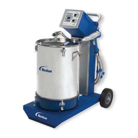
Description Section 2 Description Introduction See Figure 2-1. This manual covers all versions of the Encore LT Manual Powder Spray System: Mobile system with vibratory box feeder Mobile system with feed hopper Rail-mount system Wall-mount system Mobile System with Hopper... -
Page 14: Mobile System Components
Description Mobile System Components Mobile systems include: Encore LT manual controller Encore LT manual spray gun Encore Generation II powder feed pump Encore pump pickup tube One of the following, based on system version: Vibratory table and motor − fluidizes a 25- or 50-lb box of powder 50-lb Encore round feed hopper −... -
Page 15: Specifications
598.5 mm (23.5 in.) Weight: 46.7 kg (103 lbs) Mobile System with 50Lb. Feed Hopper Height: 995 mm (35.2 in.) Length: 812 mm (32 in.) Wheel Base: 598.5 mm (23.5 in.) Weight: 50.4 kg (111 lbs) Part 1604857-04 E 2014 Nordson Corporation... -
Page 16: Equipment Labels
Powder Spray Gun Certification Labels Controller Certification Label ENCORE LT EN 50050 FM11ATEX0057X (2) 3 D Ex tc IIIC T60C Dc T = +15 to +40C NORDSON CORP. AMHERST, OH, USA Vn=100−250Vac 7n=50−60Hz Pn=100VA OUTPUT: V = +19V Io = +1.0A (peak) (peak) WARNING −... -
Page 17: System Setup
5. Rail bracket 8. M8 x 70 screws 2. M5 x 12 screws 6. Rail 9. #10 dished lock washer 3. M8 x 40 screws 7. M8 lock washers 10. Parts tray 4. M8 jam nuts Part 1604857-04 E 2014 Nordson Corporation... -
Page 18: Controller Wall Mounting
3. Use the bus-bar grounding kit to connect the controller ground stud to the booth base, as described in the grounding kit instructions. Dished Washer Figure 3-2 Wall-Mount Bracket Installation Part 1604857-04 E 2014 Nordson Corporation... -
Page 19: System Connections
Hopper** Relay VBF Power Cord* Board Line AC Power Cord Filter Powder Box* Dolly or Booth VIibrator Motor* Ground * VBF System ** Hopper System Figure 3-3 Encore LT Manual Powder System Block Diagram Part 1604857-04 E 2014 Nordson Corporation... -
Page 20: Controller Connections
(GRN/YEL) (BROWN) (BLUE) Figure 3-4 Encore LT Gun Controller Connections 1. Electrostatic ground (to cart or booth) 5. Air supply (blue, 10mm) 9. Fluidizing air (blue, 6mm, to pickup tube or hopper) 2. Vibrator motor power cord 6. -
Page 21: Vbf System Setup
3. See Figure 3-6. Install the collar (1) on the pickup tube (2) as shown. Tighten the socket-head screw to secure the collar. Figure 3-6 Collar Installation on Pickup Tube 1. Collar 3. Pickup tube 2. M5 socket head screw (black) 4. Pump mount Part 1604857-04 E 2014 Nordson Corporation... - Page 22 10. Secure the tubing to the arm with blue Nordson Velcro straps (5). Part 1604857-04...
- Page 23 System Setup Create Service Loop Here Figure 3-8 Encore LT Gun Pickup Tube and Pump Installation 1. Bulkhead union 4. Blue 8-mm atomizing tubing* 7. Powder hose 2. 6-mm black fluidizing air tubing* 5. Velcro straps 9. Blue 6-mm fluidizing tubing 3.
-
Page 24: Feed Hopper And Wall/Rail Mount System Setup
(3). NOTE: The pump is equipped with quick-connect couplings that allow you to quickly disconnect the air tubing when cleaning or repairing the pump. Pull back on the knurled coupling rings to uncouple them. Part 1604857-04 E 2014 Nordson Corporation... -
Page 25: Part
System Setup Figure 3-9 Encore LT Mobile System with Hopper − Hopper and Pump Installation 1. Vent hose 5. Pump mount 9. Blue fluidizing air tubing 2. Powder hose 6. Black flow-rate air tubing 10. Ground wire 3. Hose clamp 7. -
Page 26: Adapter Kit Or Coupling Installation − Wall/Rail Mount Systems
5. Install the Encore pump into the pump adapter with a slight twisting motion. 2. Replace With Encore Adapter 1. Remove Existing Adapter Hopper Pump Pickup Tube Coupling Assembly Pump Adapter Adapter Installation Coupling Installation Figure 3-10 Pump Mounting Part 1604857-04 E 2014 Nordson Corporation... -
Page 27: Spray Gun Connections
2. Thread the cable nut onto the receptacle and tighten the nut securely. 3. Secure the cable strain relief to the rear panel with one of the existing panel screws. Mobile System Rail/Wall Mount System Strain Relief Figure 3-11 Gun Cable Connection and Strain Relief Mounting Part 1604857-04 E 2014 Nordson Corporation... -
Page 28: Air Tubing And Powder Hose
The flow control valve can be located anywhere desired. Use a tubing cutter to make sure the tube ends are square. Air Wash Connector Flow Control Valve To Gun 4-mm Tubing Figure 3-13 Flow Control Valve and Air Wash Tubing Connection Part 1604857-04 E 2014 Nordson Corporation... -
Page 29: Bundling Tubing And Cable
5. Note the orientation of the flow indicator (5) on the top of the filter. Cut 10-mm blue air tubing to the required lengths to connect the air supply to the filter and the filter to the controller, then connect the tubing. Part 1604857-04 E 2014 Nordson Corporation... - Page 30 Figure 3-14 Air Filter Installation − Wall and Rail Mount Systems 1. 10-mm air tubing (blue) 4. Bracket 6. Release latch 2. 10-mm tube x 1/2 male connectors 5. Flow indicator 7. Customer-supplied fasteners 3. M5 screws Part 1604857-04 E 2014 Nordson Corporation...
-
Page 31: System Electrical Connections
Rail Mount Systems: Locate the ESD grounding block kit. Follow the kit instructions to install the grounding block to the grounded spray booth base. Connect the flat braided ground cable from the controller ground stud to the grounding block. Part 1604857-04 E 2014 Nordson Corporation... -
Page 32: Controller Configuration
Flow-Rate Air Select Charge (Classic) Mode Settings Powder Flow Rate (Smart Flow) Setting/Display KV/A Setting/Display KV/uA Selection Smart Flow Mode Control Indicator Atomizing Air (Classic) Total Flow (Smart Flow) Setting/Display Figure 3-16 Controller Interface Part 1604857-04 E 2014 Nordson Corporation... -
Page 33: Function Settings
Adjust the delay as required for your application. Exiting Configuration Mode To accept all function values and exit Configuration Mode, press the Enable/Disable button. The controller can now be operated normally. Part 1604857-04 E 2014 Nordson Corporation... - Page 34 3-18 System Setup Part 1604857-04 E 2014 Nordson Corporation...
-
Page 35: Operation
European Union, ATEX, Special Conditions for Safe Use 1. The Encore LT Controllers and Mobile Powder Systems shall be used over the ambient temperature range of +15_C to +40_C with the Encore LT Powder Electrostatic Manual Applicators. -
Page 36: Displays And Leds
The electrostatic setpoints for the Select Charge Modes are: Re-Coat 100 kV, 15 A Metallics 50 kV, 50 A Deep Recesses 100 kV, 60 A NOTE: Pressing the + or − keys have no effect when a Select Charge mode is selected. Part 1604857-04 E 2014 Nordson Corporation... -
Page 37: Custom Electrostatic Mode
A. Press the + or − buttons to select the desired kV setpoint. The longer a button is pressed the faster the units change. The valid STD range is 0 or 25−100 kV. Part 1604857-04 E 2014 Nordson Corporation... -
Page 38: Classic Afc Mode
Since the air flow values are continuously monitored and adjusted, a slight high frequency pulsation in the air lines is normal. Part 1604857-04 E 2014 Nordson Corporation... -
Page 39: Smart Flow Mode Settings
At 7 bar (100 psi) supply pressure: Total Flow Flow Air Flow Air Pressure Atomizing Air Pressure Setting % Setting % bar (psi) bar (psi) 1.7 (25) 1.7 (25) 0.86 (12.5) 2.6 (37.5) Part 1604857-04 E 2014 Nordson Corporation... -
Page 40: Classic Flow Mode Settings
At 7 bar (100 psi) supply pressure: Flow Atomizing Flow Air Pressure Atomizing Air Pressure Setting % Setting % bar (psi) bar (psi) 1.7 (25) 1.7 (25) 2.7 (40) 0.689 (10) Part 1604857-04 E 2014 Nordson Corporation... -
Page 41: Spray Gun Operation
4. Make sure the spray gun is not triggered, then turn on controller power. The displays and icons on the controller interface should light. Part 1604857-04 E 2014 Nordson Corporation... -
Page 42: Purging
NOTE: The vibrator table can hold a maximum 25 kg (50 lb) box of powder. 1. See Figure 4-6. Lift the pickup tube up and swing the tube bracket down and under the pickup tube end to hold it in place on the arm. Part 1604857-04 E 2014 Nordson Corporation... -
Page 43: Vibratory Box Feeder Operation
Enable/Disable button or turn off controller power. To configure the system for a vibratory box feeder, change the VBF delay time, or set the vibrator motor to continuous operation, refer to page 3-16. Part 1604857-04 E 2014 Nordson Corporation... -
Page 44: Changing Flat Spray Nozzles
6. Press the Enable/Disable button to wake up the controller. NOTE: To clean nozzles, use the Recommended Cleaning Procedure for Powder Contact Parts on page 4-13. Nozzle Nut Flat Spray Nozzle Electrode Assembly Figure 4-7 Changing a Flat Spray Nozzle Part 1604857-04 E 2014 Nordson Corporation... -
Page 45: Changing Conical Nozzles And Deflectors
8. Press the Enable/Disable button to wake up the controller. NOTE: To clean nozzles, use the Recommended Cleaning Procedure for Powder Contact Parts on page 4-13. Conical Electrode Holder Electrode Assembly Deflector Nozzle Nozzle Nut Figure 4-8 Changing a Conical Nozzle Part 1604857-04 E 2014 Nordson Corporation... -
Page 46: Installing The Optional Pattern Adjuster Kit
3. Turn off the system air supply and relieve the system air pressure. 4. If shutting down for the night or a longer period of time, disconnect power to the controller. 5. Perform the Daily Maintenance procedures on page 4-13. Part 1604857-04 E 2014 Nordson Corporation... -
Page 47: Maintenance
Failure to observe this warning may result in personal injury. Recommended Cleaning Procedure for Powder Contact Parts Nordson Corporation recommends using an ultrasonic cleaning machine and Oakiter BetaSolv emulsion cleaner to clean spray gun nozzles and powder path parts. -
Page 48: Maintenance
Refer to Parts for the replacement filter element part number. (Periodically) System Daily: Make sure the system is securely connected to a true earth ground before Grounds spraying powder. Periodically: Check all system ground connections. Part 1604857-04 E 2014 Nordson Corporation... -
Page 49: Troubleshooting
These troubleshooting procedures cover only the most common problems. If you cannot solve a problem with the information given here, contact your contact Nordson technical support at (800) 433−9319 or your local Nordson representative for help. Controller Faults... -
Page 50: General Troubleshooting Chart
Replace worn parts. Plugged electrode assembly or Remove and clean the electrode powder path assembly. Remove and clean the spray gun powder path (inlet tube, elbow, and outlet tube) if necessary. Continued... Part 1604857-04 E 2014 Nordson Corporation... - Page 51 Orifice size is .25−.3 mm. Clean with an appropriate tool. Continued... Part 1604857-04 E 2014 Nordson Corporation...
- Page 52 Clean as necessary with compressed air. Flow and atomizing air tubing Check flow and atomizing air tubing connections reversed routing and switch if incorrect. Continued... Part 1604857-04 E 2014 Nordson Corporation...
- Page 53 The cable should be inserted past the white line marked towards the end of the cable. Push the black bar back into the white connector to secure. Part 1604857-04 E 2014 Nordson Corporation...
-
Page 54: Spray Gun Power Supply Resistance Test
The resistance should be 19−21 megohms. If the resistance is out of this range replace the electrode assembly. 19−21 Megohms Figure 5-11 Electrode Assembly Resistance Test Part 1604857-04 E 2014 Nordson Corporation... -
Page 55: Gun Cable Continuity Test
(N/C) J1−1 J1−3 J3−2 J3−4 (ORANGE) (RED) (ORANGE) (WHITE) J3−3 (GREEN) J2−1 J2−3 J1−6 (RED) J1−4 (YELLOW) J2−2 (GREEN) (WHITE) (BLACK) J1−5 J2 (FACE VIEW) (YELLOW) POWER SUPPLY CONNECTOR Figure 5-12 Gun Cable Wiring Part 1604857-04 E 2014 Nordson Corporation... - Page 56 Troubleshooting Part 1604857-04 E 2014 Nordson Corporation...
-
Page 57: Repair
Power Supply Connectors Trigger Connectors Figure 6-1 Gun Disassembly 1. Nozzle nut 8. Cover 11. M3 x 30 screw 2. Nozzle 9. Housing 12. M3 x 20 screw 3. Electrode assembly 10. Hook Part 1604857-04 E 2014 Nordson Corporation... -
Page 58: Gun Disassembly (Contd)
Removing the Power Supply from the Gun Body 3. Slide the new power supply into the upper cavity of the gun body, guiding the gun body ribs between the raised grooves on the top of the power supply. Part 1604857-04 E 2014 Nordson Corporation... -
Page 59: Powder Path Replacement
O-rings are undamaged. Figure 6-4 Powder Path Replacement 4. Outlet tube 14. Air wash tubing 24. Handle 12. M3 x 20 screws 15. Ground pad 25. Inlet tube 13. Gun body 18. Elbow 27. Handle base Part 1604857-04 E 2014 Nordson Corporation... -
Page 60: Powder Path Installation
6. Install the nozzle (2) on the electrode assembly, making sure the keys in the electrode assembly slide into the slots on the nozzle. 7. Install the nozzle nut (1) over the nozzle and rotate clockwise to secure. Part 1604857-04 E 2014 Nordson Corporation... -
Page 61: Cable Replacement
Power Supply Trigger VIEW A Ground VIEW B VIEW C Figure 6-6 Cable Replacement 12. M3 x 20 screws 16. M3 x 6 screw 27. Handle base 15. Ground pad 17. Lock washer 30. E-ring Part 1604857-04 E 2014 Nordson Corporation... -
Page 62: Cable Installation
4. Remove the spray trigger (20), actuator (21, not shown), and purge trigger (19) from the handle. Gusset Figure 6-7 Removing the Axle and Triggers from the Handle Part 1604857-04 E 2014 Nordson Corporation... -
Page 63: Switch Installation
(25) and through the slot in the trigger recess. 2. Peel off the small piece of tape holding the ribbon cable against switch. Figure 6-9 Installing the Trigger Switch − Steps 1 and 2 Part 1604857-04 E 2014 Nordson Corporation... -
Page 64: Switch Installation (Contd)
9. Connect the trigger switch connector to the round cable connector, then tuck the connectors back up to the handle. 10. Re-install the ground cover as described in Cable Installation steps 5−7 on page 6-6. Part 1604857-04 E 2014 Nordson Corporation... -
Page 65: Controller Repair
Refer to Section 5, Troubleshooting, for the controller electrical schematic and harness connections. Refer to Section 7, Parts for repair kits. Figure 6-12 Controller Front Panel 1. Bezel 2. Keypad 3. Main control board Part 1604857-04 E 2014 Nordson Corporation... -
Page 66: Rear Panel Components
1. Manifold assembly 4. Line filter 7. Air wash air solenoid valve 2. Relay board 5. Fluidizing air solenoid valve 8. Flow-rate air regulator 3. Power supply 6. Purge air solenoid valve 9. Atomizing air regulator Part 1604857-04 E 2014 Nordson Corporation... -
Page 67: Vibrator Motor Replacement
115V MOTOR 230V MOTOR L1 F M1 M2 M3 M1 M2 M3 M1 M2 M3 Jumper JP1 for 115V Motor VBF POWER CORD WIRING Remove Jumper for 230V Motor Figure 6-14 Vibrator Motor Connections Part 1604857-04 E 2014 Nordson Corporation... - Page 68 6-12 Repair Part 1604857-04 E 2014 Nordson Corporation...
-
Page 69: Parts
Support Center at (800) 433-9319 or contact your local Nordson representative. This section covers parts for the Encore LT spray gun, controller, system components and parts, powder and air tubing, and options. Refer to the following manuals for additional information and optional equipment. -
Page 70: Spray Gun Parts Illustration
Parts Spray Gun Parts Illustration Figure 7-1 Exploded View of Encore LT Manual Spray Gun and Accessories Part 1604857-04 E 2014 Nordson Corporation... -
Page 71: Spray Gun Parts List
S SCREW, Philips head, M3 x 20, zinc 1088506 S KIT, body assembly, handgun, Encore 1088558 S FILTER ASSEMBLY, handgun 1106871 S HANDLE, ground pad, handgun, Encore LT/XT 983520 S WASHER, lock, internal, M3, zinc 982427 S MACHINE SCREW, pan head, recessed, M3 x 6, zinc... -
Page 72: Spray Gun Options
NOTE A: This pattern adjuster kit is only for use with a lance extension. See page 7-8 for the standard pattern adjuster kit. B: Refer to the instruction sheet 1102764 shipped with the kit for instructions. NS: Not Shown Part 1604857-04 E 2014 Nordson Corporation... -
Page 73: Flat Spray Nozzles
3 mm Flat Spray 1605847 1605848 6 mm Flat Spray 4 mm Flat Spray Figure 7-2 Flat Spray Nozzles Cross-Cut Nozzles 1605849 1605850 1605851 60 Degree Cross-cut 90 Degree Cross-cut 2.5 mm Castle Figure 7-3 Cross-cut Nozzles Part 1604857-04 E 2014 Nordson Corporation... -
Page 74: 45-Degree Corner-Spray Nozzle
Three angled slots in-line with spray gun axis Application Top and bottom coating; typically no in/out part positioning Part Description Note 1102871 NOZZLE, 45 degree, flat spray, Encore Figure 7-5 45-Degree Flat Spray Nozzle Part 1604857-04 E 2014 Nordson Corporation... -
Page 75: Conical Nozzle, Deflectors And Electrode Assembly Parts
S ELECTRODE HOLDER, Conical 1605861 Conical Electrode Assembly Figure 7-8 Conical Electrode Assembly Item Part Description Quantity Note — 1106076 ELECTRODE ASSEMBLY, conical, Encore −−−−−− S ELECTRODE SUPPORT 1106078 S ELECTRODE S ELECTRODE HOLDER, Conical 1605861 Part 1604857-04 E 2014 Nordson Corporation... -
Page 76: Pattern Adjuster Kit
26-mm conical nozzle deflectors listed on the preceding pages. Refer to the instruction sheet shipped with the pattern adjuster for installation instructions and repair parts. Part Description Note 1100012 KIT, pattern adjuster, Encore lance extension. Part 1604857-04 E 2014 Nordson Corporation... -
Page 77: Ion Collector Kit
ROD, ion collector, 15 in. — 189484 ROD, ion collector, 21 in. — 1603939 BRACKET, lance extension, ion collector, Encore A, B NOTE A: Use for 150-mm lance extension. B: Use for 300-mm lance extension. Part 1604857-04 E 2014 Nordson Corporation... -
Page 78: Controller Parts
7-10 Parts Controller Parts Front Panel and Internal Cabinet Ground Parts Illustration Rear Panel Assembly See Figures 7-11 and 7-12 for parts Figure 7-10 Controller Parts Part 1604857-04 E 2014 Nordson Corporation... -
Page 79: Front Panel And Internal Cabinet Ground Parts List
Quantity Note − 1107552 CONTROLLER ASSY, manual, Encore LT, packaged 1108279 S KIT, PCA, control, Encore LT 1108312 S PANEL, keypad, Encore LT/auto controller, packaged 982916 S SCREW, flat, socket, M5 x 10, black 982636 S SCREW, button, socket, M5 x 12, zinc... -
Page 80: Rear Panel Parts Illustration
7-12 Parts Rear Panel Parts Illustration Manifold Assembly See Figure 7-12 (this screw only) Figure 7-11 Rear Panel Parts Part 1604857-04 E 2014 Nordson Corporation... -
Page 81: Rear Panel Parts List
972808 S CONNECTOR, strain relief, 1/2 in. NPT 984192 S NUT, lock, 1/2 in. NPT, nylon 117549 S GASKET, panel, rear, Encore LT controller 982824 S SCREW, pan head, recessed, M3 x 8, with lockwasher, black 1107696 S FILTER, line, RFI power, 3A, with 0.250 QD... -
Page 82: Manifold Illustration And Parts List
1/8 unithread 1604486 S VALVE, flow control, 6 mm x 1/8 R 1108313 S MUFFLER, exhaust, 1/8 R 1107593 S GASKET, manifold, controller, Encore LT 1107597 S REGULATOR, electro-pneumatic 1099281 S VALVE, solenoid, 3 port, 24V, 0.35W Part 1604857-04... -
Page 83: System Components And Parts
1093708 GROMMET, 0.719 ID x 1.281 OD x 0.093 GR 134575 WIRE, ground (with ground clamp) 1107895 KIT, VBF pickup tube arm assembly, Encore LT 1107903 S KIT, pickup tube collar, Encore LT 1107913 KIT, rail mount, Encore LT 1600437... -
Page 84: Powder Hose And Air Tubing
C: For mobile systems only. To install the tray, remove the 2 top screws from the controller tower, install the #10 dished lock washer in the kit on one screw, then use the screws to install the tray. Part 1604857-04 E 2014 Nordson Corporation... -
Page 85: Optional Transportable Manual System
7-17 Parts Optional Transportable Manual System This system consists of an Encore LT manual powder spray system packed into a case for transportation. The following parts list consists of replacements for the components in the system. Part Description Quantity Note... - Page 86 7-18 Parts Part 1604857-04 E 2014 Nordson Corporation...
-
Page 87: Wiring Diagram
Wiring Diagram Section 8 Wiring Diagram Part 1604857-04 E 2014 Nordson Corporation... - Page 88 Wiring Diagram Part 1604857-04 E 2014 Nordson Corporation...
- Page 89 230V MOTOR M1 M2 M3 M1 M2 M3 A.C. POWER HARNESS NO.1 (GROUND JUMPER 2) 15 FT (4.6M) POWER CORD CONTROLLER CABINET NO.4 VBF POWER CORD WIRING Figure 8-1 Encore LT Manual Controller Wiring Diagram Part 1604857-04 E 2014 Nordson Corporation...
- Page 90 DECLARATION of CONFORMITY PRODUCT: Encore LT Automatic and Manual Powder Spray Systems Models: Encore Automatic Applicator and Encore LT Automatic Controllers Encore LT Manual Applicator with Encore LT Manual Controller Description: The automatic electrostatic powder spray system includes applicator, control cable, and associated controllers.
- Page 91 ZONE REV DESCRIPTION CHK RELEASE NO. DATE PRELIMINARY 07APR11 CABLE P/N WAS 1102625 PE602493 13APR11 RELEASED PE602493 03AUG11...
- Page 92 ZONE REV DESCRIPTION CHK RELEASE NO. DATE (SEE SHEET 1 FOR REVISION HISTORY.)
Need help?
Do you have a question about the Encore LT and is the answer not in the manual?
Questions and answers