Table of Contents
Advertisement
Quick Links
Advertisement
Table of Contents

Related Manuals for Huvema CRDM 3050 x 16/1


Summary of Contents for Huvema CRDM 3050 x 16/1
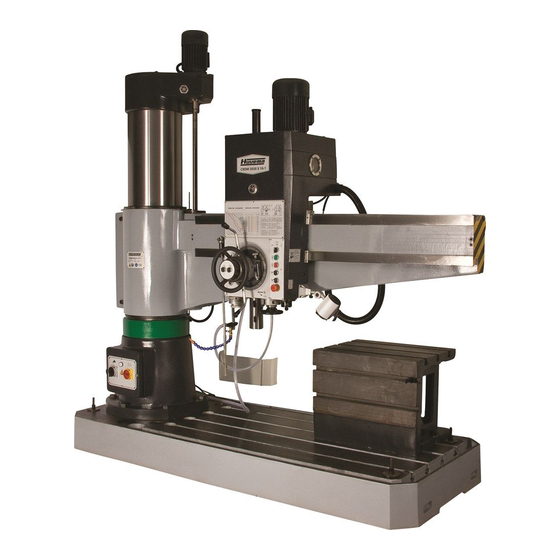
- Page 1 OPERATION MANUAL MODEL: CRDM 3050 x 16/1...
- Page 2 FOREWORD Thank you for selecting Radial Drilling Machine that we made, please completely read the operation manual for operating the machine safely and expertly. Please keep the operation manual appropriately for maintenance and operation later.
-
Page 3: Table Of Contents
CONTENTS 1. Summary of the machine 2. Installation and trial run of machine 3. Technical characteristic 4. Operation of the machine 5. Troubleshooting 6. Disposal of malfunction 7. Maintenance and adjustment of the machine 8. Hydraulic system of machine 9. Electric system of machine 12. -
Page 4: Summary Of The Machine
1. Summary of the machine 1. 1 GENERAL SAFETY RULES Operator must read the instruction before operating the machine, and the manager of safety department should assure the operator knows the requirem- ents well. WARNING! NEVER CONTACT THE CUTTERS AND OTHER DRIVING PARTS WITH HANDS IF THEY ARE STILL RUNNING. - Page 5 disconnecting the machine from the power source. 1.1.13 Always keep children away from the machine. Operating personel age must be at least 18 years. 1.1.14 Do not wear loose clothing, gloves, neckties or jewelry (rings, watches, etc). Keep the quills and the edges of the work uniform tight. Always be sure to wear safety goggles and wear safety shoes during operation.
- Page 6 1.1.28 Keep your hands away from the moving parts of the machine during operation. 1.1.29 When removing chip iron around the tooling system, avoid taking them out directly by hand, there is cutting hazards. It is safer with proper tool when doing this.
- Page 7 1.2.10 Use tools properly. Don't force a tool or an attachment to do work which was not designed. Sharp tools should be used. Deformed or dull tools should not be used. 1.2.11 Make certain the motor switch is in OFF position before connecting the machine with power supply.
- Page 8 grounding wire is reliable, phase sequence of power supply is right, emergency stop pushbutton is reliable. 1.2.26 Must clamp workpiece and cutter securely, but excessively cut workpiece. 1.2.27 Must clamp the arm, column, headstock securely, otherwise will result in injury. 1.2.28 Select revolving speed and feed on the table of plate according to the machining material and different diameter of drill, otherwise may cause injury to the machine.
- Page 9 1.2.40 Switch off the main switch before opening the electrical door. 1.2.41 User shall add guard according to the size and shape of the workpiece to avoid causing danger that coolant and scrap iron splash. 1.2.42 If dismantle spindle balancing device during the reparation, please be care with spring.
- Page 10 :hazardous electrical voltage. Imminent danger that will cause serious injury personnel or damage to machine. 1.4 Structure of the machine The machine consists of base, column, table, main drive mechanism, coolant, lubrication, electrical equipments and so on. Cast iron Steel φ50 φ50 Drilling...
- Page 11 Machine outside drawing Meanings of model:...
-
Page 12: Installation And Trial Run Of Machine
2.Installation and trial run of machine CAUTION: Headstock, arm, column were clamped before leaving the factory. Must open the picking box carefully, otherwise it will scratch the paint on the machine surface. After opening the picking box, check all the accessories according to the packing list, check whether there is something wrong or damaged, please inform dealer or manufacturer in time in order to solve it well. - Page 13 Figure 2.1...
- Page 14 2.2 The whole machine hoisting (Figure 2.2) Loosen the nut which tighten the working table and machine bed first when opening the box, swivel the working table 90 degrees in level, then move it to the barycenter of the machine along the longitudinal axes, then tighten the working table on the bed with the nut again, attire in the rigging, place some flexible things on the touched surface between rigging and machine to avoid abrading the machine surface, then lift the machine.
- Page 15 2.3 Installation of machine 2.3.1 Put the anchor bolts on the machine base when installing the machine, then put the machine on the groundwork, put the sizing block underlay the machine. 2.3.2 Clean the antirust oil on the base, column, arm, spindle and other surface. 2.3.3 Adjust the level initially: adjust the sequence of the sizing block according to 1,2,3,4 in groundwork picture 2.1.
- Page 16 eligible coolant. 2.3.10 move the arm up to the top of the column,then move down to the bottom, check whether the travel button is good. 2.3.11 Adjust level carefully, Adjust the sizing block according to picture 2.1(1,2,3,4) check the level of the cross and longitudinal of the base and make sure the level of the cross and longitudinal of the base is under 0.04/1000.
- Page 18 Figure 2.4...
- Page 20 Figure 2.6 Remark: L-AN32 is the same as mechanical oil 20# L-AN68 is the same as mechanical oil 40#...
- Page 21 2.4 Please read the installation manual carefully after you open the package, if you choose the machine which is disjointed packing type, install them as the required sequence. 2.4.1 Clean the dust and the antirust on the surface of each part of the machine. 2.4.2 Swing the base according to picture 2.8, put the sizing block 1-4 and base as showed in picture 2.1, screw the nut to avoid the dumpage after the arm covered the column.
- Page 22 according to the NO. on the cover and tighten it. 2.4.7.3 Main motor installation (see picture 2.5): Install the motor in a correct way and tighten the bolt, open up the junction box and connect the leads according to the NO. on the cover and tighten it. 2.4.7.4 Coolant pump installation (picture 2.5): after installing the motor and tightening the bolt, open the junction box and connect the leads according to No., cover and tighten it.
- Page 23 2.4.13 Turn on the current switch, adjust clamp force between the column and the rocker, make sure the clearance between the bore of arm and column is no more than 0.04mm after clamp. 2.4.14 Adjust the precision of each item, make sure the measure values do not exceed the values on the accuracy test list, Fill the foundation bolt with cement and sand slurry after the adjustment, fix the sizing block and machine base with cement after it is vulcanized completely in order to avoid the change of the level,...
- Page 25 Figure 2.10...
- Page 26 Figure 2.11...
- Page 28 2.5 Trial run 2.5.1 Check the phase and power switch after installing the machine . 2.5.2 Start the machine (refer to the operating instruction section) and check every part is normal, i.e. the clockwise and counterclockwise turn of spindle, spindle speed changes and neutral, spindle speed of all steps, spindle feed of all steps, start and stop of spindle, elevation and fall of arm, the clamp or looseness of headstock and column, the maximum stroke of headstock, the maximum travel of...
-
Page 29: Technical Characteristic
3. Technical characteristic 3.1 Main function: The machine is widely used to drill, enlarge holes, ream, countersinking and tapping on medium-large size cast iron and steel. Warning: Do not process flammable and explosive metal, e.g. pure aluminium and magnesium, etc. The main handles and pushbuttons are located on the headstock. - Page 30 to clamp headstock and column. The two clamp actions can carry through at the same time; The two clamp actions can carry through separately too.( pushbutton 1-6 on the panel of headstock), middle position is tight, left position is to loosen the column separately, right position is to loosen the headstock separately.
- Page 32 3.2 Main parameter of machine Specification Max. drilling diameter 50mm (2") Max. 1600mm (63") Distance from spindle centerline to column surface. Min. 350mm (13.8") Horizontal movement distance of headstock 1250mm (49.2") Distance from spindle nose Max. 1220mm (48") working table surface of base Min.
- Page 33 Figure 3.4...
-
Page 34: Operation Of The Machine
4. Operation of the machine Operate the machine only after trial run. Figure 4.1 Name headstock table base column HINT:1.Check whether locking plate in Figure 2.4 is removed; 2.Check whether joint is removed and oil pipe is connected well. (1 in Figure .2.3). 4.1 Preparation steps as following: 4.1.1 Open the main switch 4-1 on the column, then push the startup button of coolant pump 4-3(FIG. - Page 35 column (take linkage clamp as an example). 4.1.5 Loosen the clamp of the headstock and column through pushing the button 1-18; 4.1.6 Adjust the headstock to the appropriate place along the guide way of the arm through turning the handwheel 1-10; 4.1.7 Adjust the arm horizontally to the appropriate place through turning the handwheel 1-10;...
- Page 36 handwheel 1-9 to realize manual feed. 4.4 Tapping 4.4.1 Push the startup button 1-5 of main motor; 4.4.2Circumgyrate primary knob 1-12 of the spindle speed and feed knob 1-11, choose spindle speed and feed rate. 4.4.3 Circumgyrate the spindle clockwise or counterclockwise, push down the speed change handle 1-13 to speed change position for three seconds, put it up to the position of clockwise rotation, the screw thread can be drilled, after reaching preset depth, move the handle 1-13 to the position of reversal to unthread the tool.
- Page 37 and after turning the handle 1-8 to the position in the picture, turning the dial to the needed cutting depth, and aline with “0” of box size, and then turn handle 1-8 to the position in the fig.4.3, adjusting slightly until aline with “0”, and clamp handle 1-8 using clamp knob on the other end, push handle 1-7, switch on feed switch, when cutting depth reaches preset stroke value,handle 1-15 is put up automatically and complete cutting.
- Page 38 Name of switch Name 4—1 Main switch(red) 4—2 Power light 4—3 Cooling switch(black)
-
Page 39: Troubleshooting
5. Troubleshooting Symptom Possible cause Corrective action Remark Main motor Main switch is not switched Open the main switch, check on ; startup button does not does not turn the joint of the startup button; when pushing connected well; contactor does check every connected point startup not attract;... - Page 40 Headstock 1. Loosen bolt 2, clamp block 3 Check if bolt 2 loosen on the move moves when moving clamp block, and replace the Fig.7.1 inflexibly headstock, which makes the ball bearing on the clamp or does not clearance between clamp block plate.
-
Page 41: Disposal Of Malfunction
The arm can Bolt adjusted Remove side cover, appropriately, there loosen clamping nut Fig.7.3 clamped. clearance between the arm and adjust bolt 1, which not only outside of column when rocker make sure 0.04mm is in the state of clamping, the clearance, clearance limit switch is near the piston,... - Page 42 the operation, the strainer must be cleaned on time and keep the oil clean. 7.1.2 The guide way of the rocker and column should keep clean, and should often lubricate them per shift avoid injury. 7.1.3 The table and base must keep clean, the scrap iron should be cleaned in time, do not clean them directly by hand to avoid injury.
- Page 43 Figure 7.1 7.2.2 Adjustment of column clamp force The bolt 3 is used for adjusting the clearance of the inside and outside cone-shaped surface of column. Please force bolt uniformly when adjusting bolt. Use the nut 7 to adjust the column’s clamping force. If operator bears 1568N force on the end of arm, the column can’t be swiveled, but it can swivel after loosened and bear 29N horizontal strength, please screw down bolt 6 and screw nut 7.
- Page 44 Figure 7.2...
- Page 45 7.2.3 Adjustment of arm clamp force (see picture 7.3) shut off the power during elevating of arm when adjusting arm, then the arm will be lax. Adjust the bolt 1, 2, 3 and 4 befittingly to make sure the 0.04mm clearance gauge can’t insert when clamping the arm.
-
Page 46: Hydraulic System Of Machine
8. Hydraulic system of machine Hydraulic system of machine consists of control organ and clamp organ. 8.1 Control organ of hydraulic system (Figure 8.2) Control valve and preelection valve are installed at the top of headstock. Spindle speed preelection valve and feed preelection valve are six-way turning valve of 16-bit, each valve controls four differential motion oil cylinder to realize 16-step speed change. - Page 47 loose because of without the push of oil way ⑤, then it will push the friction disk heavily to push the transmission chain start, then the spindle will stop. Please joint the oil pipe as shown in the picture 8.3, to make sure the end of No.1 oil pipe into oil net when inserting No.1 oil pipe and cleaning the oil net, or else, the hydraulic pressure system will possibly destroyed, so the oil pipe can’t be used for long time.
- Page 48 model:A0B-25 power:0.09kW Flux:25L/min pump lift:4m Coolant list: Purpose Component Remark Property Drill Emulsification plaster 3~5%, soda ash 0.2 ~ 0.35 % , sodium steel nitrite 0.25~5%,water ream Emulsification plaster 3~5%, Nonflam- soda ash 0.2 ~ 0.35 % , sodium Mable, nitrite 0.25~5%,water antirust tapping...
- Page 49 headstock clamp organ column clamp organ arm clamp organ Figure 8.1...
- Page 50 Figure 8.2...
- Page 51 Commutation table of speed change oil cylinder...
-
Page 53: Electric System Of Machine
9. Electric system of machine 9.1 Summarization 9.1.1 Rated voltage:3/PE/-380/220/415V。 9.1.2 Voltage range:normal voltage is 0.9~1.1 times of rated voltage. 9.1.3 Frequency:50/60Hz. 9.1.4 Frequency range:0.99—1.01 times of rated frequency(continuous). 0.98—1.02 times of rated frequency(short-term operation). 9.1.5 Harmonic wave:the summation of 2~5 times aberrance harmonic wave do not exceed 10% of line voltage square root value;the summation of 6~30 times aberrance harmonic wave at most allows 2% of affix line voltage square root value. - Page 54 which indicates the phase sequence of machine is right, otherwise adjust the position of random two power wires. Adjust the the phase sequence of elevating motor after adjusting the phase sequence of main power. 9.2.3 Demand space that operator repair the machine: Distance from the machine is 800mm.
- Page 55 clamp, at the same time, piston pushes the limit switch SQ3 by spring reed to make switch off the AC contactor KM5, motor M3 stop turning. Limit switch SQ1(SQ1a、SQ1b)is to limit the travel of arm, limit switch SQ1(SQ1a, SQ1b)acts when arm reaches target position, AC contactor KM2 breaks, motor M2 stop turning, arm stops vertical movement.
- Page 56 Emergency stop button SB1, the machine is nonelectrified only after turning off the main power switch QS1. 9.3.8 Stop the machine: Must switch off the main power switch QS1 before repairing the machine. 9.4 Maintenance and adjustment of electrical equipments Caution:...
- Page 57 9.4.2 Preventive check To be more safety,the electrical equipment should be inspected yearly, eliminate it if checker finds fault at once. 9.4.2.1 Measurement of insulated resistance Measure main loop and control loop with 500V Megohmmeter,the insulated value is greater than 1 megohm. 9.4.2.2 Check of ground protection There is ground protection on all motors, operation panel and the electrical door, so please check whether the ground screws are screwed down.
- Page 58 Symptom Possible cause Remedy 1. Connect the switch. 1. The switch disconnects. 2. Reset relay by pushing the reset button after 2. Thermalrelay FR1 overheat or it is cool or replace the new one. Spindle trip. 3. Check power supply for proper voltage. does not 3.
- Page 61 Main Electrical Components List Code Name Specification Qty Remark Y112M-4 380/220/415V Motor 50/60Hz 3PH 4kW V1 Y90L-4 380/220/415V Motor 50/60Hz 3PH 1.5kW V1 YSJ80-4 380/220/415V 50/60Hz Motor 3PH 0.75kW V1 AOB-25 380/220/415V Cooling pump 50/60Hz 3PH 90W JBK5-160 160VA I:0-380V Control O:0-110V(110VA)、...
- Page 62 Code Name Specification Remark Pushbutton LAY7-01BN/1 red Pushbutton LAY7-10BN/2 green Pushbutton SB4-SB7 LAY7-11BN/3 black Knob LAY7-02X/3102 electromagnetic YV1-YV2 MFJ1-3(AC 110V) valve...
-
Page 63: Accuracy Test List
12. Accuracy test list... -
Page 65: Packing List
13. Packing list Name Specification Remark Elevating motor was dismantled, it Machine CRDM 3050×16/1 need to be installed by user. It is on the base of Table 630×500×500 the machine. There are 5 pieces Hexagon nut 12 pieces on the machine. Foundation bolt M24×450 6 pieces... - Page 66 (buy them according to agreement) Special attachments Name Specification Remark Drift 1, 2, 3 Each 1 MT3/1;3/2;4/3; Reduction sleeve Each1 5×4 wearing parts(along with the machine) Name Specification Remark O shape circle 7x1.9 O shape circle 9x1.9 O shape circle 11x1.9 O shape circle 13x1.9...
Need help?
Do you have a question about the CRDM 3050 x 16/1 and is the answer not in the manual?
Questions and answers