Aplex ARMPAC-6 Series User Manual
7”, 8”, 10.1”, and 12.1” fanless i.mx6 duallite arm cortex a9 hmi
Hide thumbs
Also See for ARMPAC-6 Series:
- User manual (29 pages) ,
- User manual (58 pages) ,
- User manual (42 pages)
Table of Contents
Advertisement
Quick Links
ARMPAC-6XX Series
7", 8", 10.1", and 12.1" Fanless i.MX6 DualLite ARM Cortex A9 HMI Series
User Manual
Release Date
Revision
Oct. 2017
V1.4
®2017 Aplex Technology, Inc.
All Rights Reserved.
Published in Taiwan
Aplex Technology, Inc.
15F-1, No.186, Jian Yi Road, Zhonghe District, New Taipei City 235, Taiwan
Tel: 886-2-82262881 Fax: 886-2-82262883 URL: http://www.aplextec.com/zh/home.php
Advertisement
Table of Contents

Subscribe to Our Youtube Channel
Related Manuals for Aplex ARMPAC-6 Series


Summary of Contents for Aplex ARMPAC-6 Series
- Page 1 7”, 8”, 10.1”, and 12.1” Fanless i.MX6 DualLite ARM Cortex A9 HMI Series User Manual Release Date Revision Oct. 2017 V1.4 ®2017 Aplex Technology, Inc. All Rights Reserved. Published in Taiwan Aplex Technology, Inc. 15F-1, No.186, Jian Yi Road, Zhonghe District, New Taipei City 235, Taiwan Tel: 886-2-82262881 Fax: 886-2-82262883 URL: http://www.aplextec.com/zh/home.php...
- Page 2 Revision History Reversion Date Description 2016/11/08 Official Version 2017/01/13 Add SOP of updating Firmware and Linux QT, and update power consumption and net weight. Update SBC-7112 motherboard manual to R1.2 version 2017/04/12 Modify power consumption data. 2017/07/19 Remove 5” Add 15”, 15.6” 2017/10/20 Add motherboard version Modify software/IP rating...
- Page 3 This information in this document is subject to change without notice. In no event shall Aplex Technology Inc. be liable for damages of any kind, whether incidental or consequential, arising from either the use or misuse of information in this document or in any related materials.
-
Page 4: Packing List
Packing List Accessories (as ticked) included in this package are: □ Adaptor □ Driver & manual CD disc □ Other.___________________(please specify) ARMPAC-6XX Series User Manual... -
Page 5: Safety Precautions
Safety Precautions Follow the messages below to prevent your systems from damage: ◆ Avoid your system from static electricity on all occasions. ◆ Prevent electric shock. Don‘t touch any components of this card when the card is power-on. Always disconnect power when the system is not in use. -
Page 6: Table Of Contents
Table of Contents Revision History…………………………………………………………………………………………………….1 Warning!.............…………………………….……………………2 Caution/Disclaimer…………………..………………………………………………………………………3 Packing List…………………………………….…………………………………………………....4 Safety Precautions………………………………….……………….…..……………………....5 Chapter 1 Getting Started 1.1 Features……..…………………..………………………...…………………………..6 1.2 Specifications…..………………...………………………………………………….6 1.3 Dimensions……..…………………..……………………………………………...8 1.4 Brief Description of ARMPAC-6XX…..….…..……………………….……10 1.5 VESA Mounting……………….…………..………..…...…………………..…..11 1.6 Panel Mounting…..………….…………..………..…...…………………..…..11 Chapter 2 Hardware 2.1 Motherboard Jumpers Setting and Connectors…………………...12 Chapter 3 Software images 3.1 Linux QT……………………………………....……………………...18... -
Page 7: Getting Started
Chapter 1 Getting Started 1.1 Features ARM based HMI Fanless design Flat front panel touch screen Freescale i.MX6 DualLite/Quad (option) ARM Cortex A9 Processor Onboard 1GB DDR3 DRAM Onboard 4GB eMMC Flash Wide range DC 9~36V power input ... -
Page 8: Dimensions
Resolution 800x480 800x600 1024x600 800x600 Max. Color 262K 262K 262K 262K Luminance Contrast Ratio 400: 1 500: 1 500: 1 800: 1 Viewing Angle 140(H)/110(V) 140(H)/135(V) 140(H)/120(V) 160(H)/140(V) Backlight Lifetime 40,000 hrs 40,000 hrs 25,000 hrs 50,000 hrs Touch Screen – Resistive Touch Window Type Interface Light Transmission Over 80%... -
Page 9: Figure 1.1: Dimensions Of Armpac-607(P)
1.3 Dimensions Figure 1.1: Dimensions of ARMPAC-607(P) Figure 1.2: Dimensions of ARMPAC-608(P) ARMPAC-6XX Series User Manual... -
Page 10: Figure 1.3: Dimensions Of Armpac-610(P)
Figure 1.3: Dimensions of ARMPAC-610(P) Figure 1.4: Dimensions of ARMPAC-612(P) ARMPAC-6XX Series User Manual... -
Page 11: Brief Description Of Armpac-6Xx
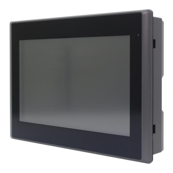
1.4 Brief Description of ARMPAC-6XX There are 7”, 8”, 10.1”, and 12.1” in fanless designed ARM based HMI, which comes with flat front panel LED backlight touch designed. It is powered by Freescele i.MX6 DualLite/Quad (option) ARM Cortex A9 processor, 1GB DDR3 onboard memory, and 4GB eMMC NAND flash onboard. -
Page 12: Vesa Mounting
1.5 VESA Mounting The ARMPAC-6XX series is designed to be VESA mounted as shown in Picture. Just carefully place the unit through the hole and tighten the given screws from the rear to secure the mounting. Figure 1.9: ARMPAC-6XX Series VESA Mounting 1.6 Panel Mounting There are four holes located along the four sides of the HMI. -
Page 13: Hardware
Chapter 2 Hardware 2.1 Motherboard Jumpers Setting and Connectors 1. J5: (Micro USB OTG 5P Connector), it is used to download and connect to Android App. 2. USB1: (Double stack USB type A), Front USB connector, it provides 2 USB2.0 ports, High-speed USB 2.0 allows data transfers up to 480 Mb/s, support USB full-speed and low-speed signaling. - Page 14 5. COM1 (Type DB9), Front serial port, standard DB9 Male serial port is provided to make a direct connection to serial devices. Used the SP339E as the driver, which is an advanced multiprotocol transceiver supporting RS-232, RS-485 and RS-422. Pin# Signal Name DCD3-_422TX-_485- RXD3_422TX+_485+...
- Page 15 Signal Name Pin# Pin# Signal Name 5WSX- M2(U17) 9. SIM1: (SIM Card Socket), Support SIM Card devices. 10. LVDS1: (1.25mm Pitch 2*10 Connector, DF13-20DP-1.25V), For 18-bit LVDS1 output connector. Signal Name Pin# Pin# Signal Name VCC_LVDS0 VCC_LVDS0 LVDS0_TX0_N LVDS0_TX0_P LVDS0_TX1_N LVDS0_TX1_P LVDS0_TX2_N LVDS0_TX2_P...
- Page 16 BKLT_CTRL1 BKLT_EN_OUT1 VCC_BL1 VCC_BL1 12. INVT1: (2.0mm Pitch 1*6 box Pin Header), Backlight control connector for LVDS1. Pin# Signal Name VCC_BL0 VCC_BL0 BKLT_EN_OUT0 BKLT_CTRL0 13. BT1: (1.0mm Pitch 1*2 box Pin Header), 3.0V Li battery is embedded to provide power for RTC.
- Page 17 15. J20: (1.0mm Pitch 1*2 box Pin Header), Reserved to connect switch reset button.. 16. MPCIE1: (Mini PCIe Socket 52Pin), mini PCIe socket, it is located at the top, it supports mini PCIe devices with USB2.0 and SIM and SMBUS and PCIe signal. MPCIe card size is 30*30mm or 30*50.95mm.
- Page 18 21. J4: (2.0mm Pitch 1*3 Pin Header), LVDS2 jumper setting. It is used to provide 5V or 12V voltage to VCC_BL1. J4 Pin# Function Close 1-2 VCC_ BL1 = 5V (option) Close 2-3 VCC_ BL1 = 12V (default) 22. SW2: Dial Switch , it is used to select the voltage for BKLT_CTRL0 and BKLT_EN_OUT0.
-
Page 19: Chapter 3 Software Images
Chapter 3 Software images 3.1 Linux QT 1. Linux 3.0.35+QT4.85. ARMPAC-6XX Series User Manual... -
Page 20: Android
3.2 Android 1. Android 4.2.2 (Kernel:3.0.35) ARMPAC-6XX Series User Manual... - Page 21 Android 5.1.1 ( kernel:3.14.52 ) ARMPAC-6XX Series User Manual...
Need help?
Do you have a question about the ARMPAC-6 Series and is the answer not in the manual?
Questions and answers