Table of Contents
Advertisement
Quick Links
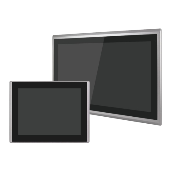
ARCHMI-9XXB Series
12.1", 12.1W", 15", 15.6", 17", 18.5", 19", 21.5", and 32" Intel Whiskey Lake
Fanless Industrial Compact Size Panel PC
User Manual
Release Date
Revision
Sep.2022
V1.1
®2022 Aplex Technology, Inc.
All Rights Reserved.
Published in Taiwan
Aplex Technology, Inc.
15F-1, No.186, Jian Yi Road, Zhonghe District, New Taipei City 235, Taiwan
Tel: 886-2-82262881 Fax: 886-2-82262883
URL:
http://www.aplextec.com/zh/home.php
Advertisement
Table of Contents

Related Manuals for Aplex ARCHMI-9 B Series


Summary of Contents for Aplex ARCHMI-9 B Series
- Page 1 Fanless Industrial Compact Size Panel PC User Manual Release Date Revision Sep.2022 V1.1 ®2022 Aplex Technology, Inc. All Rights Reserved. Published in Taiwan Aplex Technology, Inc. 15F-1, No.186, Jian Yi Road, Zhonghe District, New Taipei City 235, Taiwan Tel: 886-2-82262881 Fax: 886-2-82262883 URL: http://www.aplextec.com/zh/home.php...
-
Page 2: Revision History
Revision History Reversion Date Description 2022/04/06 Initiation 2022/9/21 Updated power consumption and net weight ARCHMI-9XXB Series User Manual... -
Page 3: Warning
Disclaimer This information in this document is subject to change without notice. In no event shall Aplex Technology Inc. be liable for damages of any kind, whether incidental or consequential, arising from either the use or misuse of information in this document or in any related materials. -
Page 4: Safety Precautions
Safety Precautions Follow the messages below to prevent your systems from damage: ◆ Avoid your system from static electricity on all occasions. ◆ Prevent electric shock. Don‘t touch any components of this card when the card is power-on. Always disconnect power when the system is not in use. ◆... -
Page 5: Table Of Contents
Table of Contents Revision History ..........................1 Warning! ............................2 Safety Precautions ..........................3 Chapter 1 System Product ......................6 Features ..........................6 Specifications .......................... 6 COM port definition ......................... 8 Standard LCD ........................... 9 High Brightness LCD ....................... 10 Power Consumption and PoE Application ................. - Page 6 IST OF IGURES 1.1 D ARCHMI-912BP/BR (H) ........................12 IGURE IMENSIONS OF 1.2 D ARCHMI-912WBP/WBR (H) ......................12 IGURE IMENSIONS OF 1.3 D ARCHMI-915BP/BR (H) ........................13 IGURE IMENSIONS OF 1.4 D ARCHMI-916BP/BR (H) ........................13 IGURE IMENSIONS OF 1.5 D ARCHMI-917BP/BR (H) ........................
-
Page 7: Chapter 1 System Product
System Product Chapter 1 1.1 Features Industrial Compact Size Panel PC Flat front panel touch screen Fanless Design Intel Whiskey Lake i3-8145UE/i5-8365UE CPU (4305UE, i7-8665UE series by project) One SO-DIMM Slot up to 32GB DDR4 2400MHz ... - Page 8 Option TB-528 Series: 1. 4 x USB2.0 type A (TB-528U4) 2. 1 x COM(RS-232) + 2 x USB2.0 + 1 x Mini PCIe slot(TB-528C1U2P1) 3. 2 x CAN (TB-528CAN2) 4. 2 x COM(RS-232) + 1 x Mini-PCIe slot (TB-528C2ME1) UPS Battery (Turbo OFF in BIOS) Speaker (Through TB-38) Auto Dimming (Through TB-38) GPIO (4xDI, 4xDO, through TB-542)
-
Page 9: Com Port Definition
Chassis Color RAL 9007 IP Rating Front Panel IP66 Operating System Support OS Support Windows 10 IoT Enterprise Yocto Linux Linux Ubuntu 20.04 above Environmental Operating 0~50°C/-20℃ to 60℃ optional Temperature Storage Temperature -20~60°C Humidity 10 to 95% @ 40°C, non-condensing Certification Meet CE / FCC Class A 1.3 COM port definition... -
Page 10: Standard Lcd
1.4 Standard LCD ARCHMI- ARCHMI- ARCHMI- ARCHMI- ARCHMI- 912BP/R 912WBP/R 915BP/R 916BP/R 917BP/R Display Type 12.1” TFT LCD 12.1”W TFT LCD 15” TFT LCD 15.6” TFT LCD 17” TFT LCD Max. Resolution 800 x 600 1280 x 800 1024 x 768 1366 x 768 1280 x 1024 1024 x 768... -
Page 11: High Brightness Lcd
1.5 High Brightness LCD ARCHMI- ARCHMI- ARCHMI- ARCHMI- ARCHMI- 912BP/RH 912WBP/RH 915BP/RH 916BP/RH 917BP/R/GH Display Type 12.1” TFT LCD 12.1”W TFT LCD 15” TFT LCD 15.6” TFT LCD 17” TFT LCD Max. Resolution 800 x 600 1280 x 800 1024 x 768 1366 x 768 1280 x 1024 1024 x 768... -
Page 12: Power Consumption And Poe Application
* y* does not apply in Linux OS. * We suggest to use the adapter that Aplex approved. If you would like to adopt your own power supply or adapter, please add another 20-30% from the above power consumption to make sure the system can work correctly. -
Page 13: Dimensions
1.7 Dimensions Figure 1 Dimensions of ARCHMI-912BP/BR (H) Figure 2 Dimensions of ARCHMI-912WBP/WBR (H) ARCHMI-9XXB Series User Manual... - Page 14 Figure 3 Dimensions of ARCHMI-915BP/BR (H) Figure 4 Dimensions of ARCHMI-916BP/BR (H) ARCHMI-9XXB Series User Manual...
- Page 15 Figure 5 Dimensions of ARCHMI-917BP/BR (H) Figure 6 Dimensions of ARCHMI-918BP/BR (H) ARCHMI-9XXB Series User Manual...
- Page 16 Figure 7 Dimensions of ARCHMI-919BP/BR (H) Figure 8 Dimensions of ARCHMI-921BP/BR (H) ARCHMI-9XXB Series User Manual...
-
Page 17: Brief Description Of Archmi-9Xxb Series
Figure 9 Dimensions of ARCHMI-932BP 1.8 Brief Description of ARCHMI-9XXB Series There are 12.1” ~ 32” Industrial Compact Size Panel PC in ARCHMI-9XXB series, which comes with flat front panel touch screen and fanless design. It is powered by Intel 8 Generation Core i3/i5(option) CPU Processors with one SO-DIMM DDR4 slot, up to 32GB 2400 MHz. - Page 18 Figure 10 Front View of ARCHMI-912BP/R(H) Figure 11 Rear View of ARCHMI-912BP/R(H) Figure 12 Front View of ARCHMI-915BP/R(H) ARCHMI-9XXB Series User Manual...
- Page 19 Figure 13 Rear View of ARCHMI-915BP/R(H) Figure 14 Front View of ARCHMI-916BP/R(H) Figure 15 Rear View of ARCHMI-916BP/R(H) ARCHMI-9XXB Series User Manual...
- Page 20 Figure 16 Front View of ARCHMI-917BP/R(H) Figure 17 Rear View of ARCHMI-917BP/R(H) Figure 18 Front View of ARCHMI-918BP/R(H) ARCHMI-9XXB Series User Manual...
- Page 21 Figure 19 Rear View of ARCHMI-918BP/R(H) Figure 20 Front View of ARCHMI-919BP/R(H) Figure 21 Rear View of ARCHMI-919BP/R(H) ARCHMI-9XXB Series User Manual...
- Page 22 Figure 22 Front View of ARCHMI-921BP/R(H) Figure 23 Rear View of ARCHMI-921BP/R(H) Figure 24 Front View of ARCHMI-932BP ARCHMI-9XXB Series User Manual...
- Page 23 Figure 25 Rear View of ARCHMI-932BP ARCHMI-9XXB Series User Manual...
-
Page 24: Installation Of Hdd For 32
1.9 Installation of HDD for 32” Step 1 There are 4 screws to deal with when enclosing or removing the chassis. Gently remove 4 screws. Step 2 You can put or remove HDD into the machine by pulling the HDD bracket. Step 3 You can remove HDD by unscrewing 4 screws in the HDD bracket. -
Page 25: Vesa Mounting
1.10 VESA Mounting The ARCHMI-9xxB series is designed to be VESA mounted as shown in Picture. Just carefully place the unit through the hole and tighten the given screws from the rear to secure the mounting. Figure 26 ARCHMI-9xxB Series VESA Mounting 1.11 Panel Mounting There are four holes located along the four sides of the HMI. -
Page 26: Chapter 2 Hardware
Hardware Chapter 2 SBC-7124 is a 4" industrial motherboard developed on the basis of Intel Whiskey Lake-U Processor, which provides abundant peripheral interfaces to meet the needs of different customers. Also, it features dual GbE ports, 6-COM ports and one M.2 M-Key configuration, one DP port, one LVDS interface. - Page 27 (USB3.2:USB3-1/USB3- 2/USB3_3/USB3_4,USB2.0:USB1/2/3/4) 2 x USB 2.0 Pin header for CN3 (USB5/USB6) 1 x USB 2.0 Pin header for CN1 (USB7) 1 x USB 2.0 Pin header for CN2 (USB8) 1 x USB 2.0 for M-PCIE1 (USB9) 1 x USB 2.0 for PM6000 (USB10) 1 x DB9-M Connector for external (COM1) 1x RS232 port, Pin1 w/5V/12V/RTS select (COM1-1) Serial...
- Page 28 1 x DP Port 1 x Audio Jack (Line out) Infineon’s Trusted Platform Module (TPM 2.0) *Note: Only support Windows 10 IOT Operating: -20℃ to 70℃ Temperature Storage: -40℃ to 85℃ Humidity 10% - 90%, non-condensing, operating Power 24V/1.6A (Intel i3-8145UE Processor with 16GB DDR4/HDD) 24V/2.0A (Intel i5-8365UE Processor with 16GB DDR4/HDD) Consumption Meet CE/FCC class A...
-
Page 29: Board Dimensions
2.2 Board Dimensions (units :mm) ARCHMI-9XXB Series User Manual... -
Page 30: Jumpers And Connectors Location
2.3 Jumpers and Connectors Location Board Top Board Bottom 2.4 Jumpers Setting and Connectors 1. CPU1: (FCBGA1528), onboard Intel Whiskey Lake-UE Processors. ARCHMI-9XXB Series User Manual... - Page 31 Processor Model Number Cores/ Embedded Intel VPro Remarks Threads ● ○ SBC-7124-I3-8145UE I3-8145UE 2.20 up to 12.5W 3.90GHz ● ● SBC-7124-I5-8365UE I5-8365UE 1.60 up to 12.5W option 4.10GHz ● ● SBC-7124-I7-8665UE I7-8665UE 1.70 up to 12.5W option 4.40GHz ● ○ SBC-7124-4305UE Celeron 2.0GHz...
- Page 32 SBC-7124-I7-8665UE 2400 MHz SBC-7124-4305UE 2133 MHz 5. BAT1 : (1.25mm Pitch 1x2 Wafer Pin Header, SMD) 3.0V Li battery is embedded to provide power for CMOS. CMOS clear operation will permanently reset old BIOS settings to factory defaults. Pin# Signal Name Pin1 Ground PIN2...
- Page 33 Utility to load optimal defaults. e) After the above operations, save changes and exit BIOS Setup. 7. BAT2: (2.0mm Pitch 1x10 Wafer Pin Header),Smart battery Interface. Pin# Signal Name Pin1 VCC_BAT1 Pin2 VCC_BAT1 Pin3 VCC_BAT1 Pin4 SMB_DAT_SW Pin5 SMB_CLK_SW Pin6 BAT1_TEMP Pin7 Ground...
- Page 34 9. BT1: Power on/off button, They are used to connect power switch button. The two pins are disconnected under normal condition. You may short them temporarily to realize system startup & shutdown or awaken the system from sleep state. 10. LED1/LED2/LED3/LED4/LED5/LED6/LED7/LED8/LED9: LED1: LED STATUS.
- Page 35 1920*1080(option) …… 13. INVT1: (2.0mm Pitch 1x6 wafer Pin Header), Backlight control connector for LVDS. Pin# Signal Name +DC12V_LVDS +DC12V_LVDS Ground Ground BKLT_EN_OUT BKLT_PWM_OUT 14. CN1: (1.25mm Pitch 2x20 Connector, DF13-40P),For 18/24-bit LVDS output connector,Fully supported by Parad PS8625(DP to LVDS), the interface features dual channel 24-bit output.
- Page 36 LB_D2_P LB_D2_N LB_D3_P LB_D3_N LB_CLKP LB_CLKN USB7 Ground Ground (option) USB7_P USB7_N 5V_S5_USB 5V_S5 Power LED PWR_LED+ Ground 15. DP1: (DP Connector), Interface connector. Display Port 16. SW1(PIN5): SW1-5(Switch),Touch jumper setting. SW1(Switch) Touch (TCH1) SW1-5 OFF (Default) Enable SW1-5 ON (option) Disable 17.
- Page 37 18. JP2: (2.0mm Pitch 2x3 Pin Header),COM1 jumper setting, pin 1~6 are used to select signal out of pin 1 of COM1 port. JP1 Pin# Function Close 1-2 COM1 Pin1 RTS (Default) Close 3-4 COM1 Pin1: DC+5V (option) Close 5-6 COM1 Pin1: DC+12V (option) Warning: 5V/12V located in Pin 1 of COM 1.
- Page 38 20. SATA_P1: (2.5mm Pitch 1x2 box Pin Header), One onboard 5V output connector are reserved to provide power for SATA devices. Pin# Signal Name 5V_S0 (+DC5V output) Ground Note: Output current of the connector must not be above 1A. 21. SATA1: SATA Connectors, one SATA connector are provided, with transfer (SATA 7Pin), speed up to 6.0Gb/s.
- Page 39 27. F_AUDIO1: (2.0mm Pitch 2X6 Pin Header), Front Audio, An onboard Realtek ALC888S-VD2 codec is used to provide high-quality audio I/O ports. Line Out can be connected to a headphone or amplifier. Line In is used for the connection of external audio source via a Line in cable.
- Page 40 Each USB Type A Receptacle (2 Ports) Current limited value is 2.0A. If the external USB device current exceeds 1.5A, please separate connectors into different Receptacle. 31. LAN1: (RJ45 Connector), Rear LAN port, Two standard 10/100/1000M RJ-45 Ethernet ports are provided. Used intel I219-LM chipset, LINK LED (green) and ACTIVE LED (green or orange) respectively located at the left-hand and right-hand side of the Ethernet port indicate the activity and transmission state of LAN.
- Page 41 GPIO_IN4 GPIO_IN3 SIO_GP33 SIO_GP32 GPIO_OUT2 GPIO_OUT SIO_GP35 SIO_GP34 GPIO_OUT4 GPIO_OUT SIO_GP37 SIO_GP36 Ground 11 Ground 485 or 422 485 or 422 485+_422TX5+ 485-_422TX5- (COM5) (COM5) 422_RX5+ 422_RX5- 485 or 422 485 or 422 485+_422TX6+ 485-_422TX6- (COM6) (COM6) 422_RX6+ 422_RX6- 21 HDD_LED+ HDD LED 5V_S0 23 5V_S5...
- Page 42 37. CN3: (1.27mm Pitch 2x30 Female Header),For expand output connector,It provides four GPIO,two USB 2.0, one SPI, two Uart,one PCIex1,one SMbus, connected to the TB-528 riser Card. Function Signal Name Pin# Signal Name Function 5V_S5_USB 5V_S5_USB 5V_S5_USB 5V_S5_USB USB0506_O PS_ON_ALL- USB5 USB5 USB5_N...
-
Page 43: Chapter 3 Bios Setup Description
BIOS Setup Description Chapter 3 3.1 Operations after POST Screen After CMOS discharge or BIOS flashing operation. Press [Delete] key to enter CMOS Setup. After optimizing and exiting CMOS Setup Press F11 to load default values and continue 0085 3.2 BIOS SETUP UTILITY Press [Delete] key to enter BIOS Setup utility during POST, and then a main menu containing system summary information will appear. -
Page 44: Main Settings
3.3 Main Settings Aptio Setup Utility – Copyright (C) 2021 American Megatrends, Inc. Main Advanced Chipset Security Boot Save & Exit BIOS Information Choose the system default BIOS Vendor American Megatrends Language Core Version 5.13 Compliancy UEFI 2.7; PI 1.6 Project Version 7124V 1.08 x64 EC VERSION... -
Page 45: Advanced Settings
3.4 Advanced Settings Aptio Setup Utility – Copyright (C) 2021 American Megatrends, Inc. Main Advanced Chipset Security Boot Save & Exit CPU Configuration ►CPU Configuration Parameters ►Power & Performance ►Thermal Configuration ►AMT Configuration ►Trusted Computing ►ACPI Settings ►NCT6106 Super IO Configuration →←: Select Screen ►NCT6106 HW Monitor ↑↓... - Page 46 CPU Flex Ratio Override [Disabled] CPU Flex Ratio Settings Hardware Prefetcher [Enabled] Adjacent Cache Line Prefetch [Enabled] Intel (VMX)Virtualization Technology [Enabled] PECI [Enabled] Active Processor Cores [All] BIST [Disabled] AP threads Idle Manner [MWAIT Loop] [Enabled] MachineCheck [Enabled] MonitorMWait [Enabled] Intel Trusted Execution Technology [Disabled] Alias Check Request...
- Page 47 Interrupt Redirection Mode [PAIR with Fixde Priority] Selection Timed MWAIT [Disabled] ►Custom P-state Table EC Turbo Control Mode [Disabled] Energy Performance Gain [Disabled] EPG DIMM Idd3N EPG DIMM Idd3P ►Power Limit 3 Settings Power Limit 3 Override [Disabled] ►CPU Lock Configuration CFG Lock [Enabled] Overclocking Lock...
- Page 48 Active Trip Point 0 Fan Speed Active Trip Point 1 [55 C] Active Trip Point 1 Fan Speed Passive Trip Point [95 C] Passive TC1 Value Passive TC2 Value Passive TSP Value Active Trip Points [Enabled] Passive Trip Poinst [Disabled] Critical Trip Points [Enabled] PCH Temp Read...
- Page 49 Pending operation [None] Platform Hierarchy [Enabled] Storage Hierarchy [Enabled] Endorsement Hierarchy [Enabled] TPM2.0 UEFI Spec Version [TCG_ 2] Physical Presence Spec a Version [1.3] TPM 20 InterfaceType [TIS] Device Select [Auto] 3.4.6 ACPI Settings Enable ACPI Auto Configuration: [Disabled] [Enabled] Enable Hibernation: [Enabled] [Disabled]...
- Page 50 Serial port [Enabled] [Disabled] Device Settings IO=3E8h; IRQ=6; Change Settings [Auto] ►Serial Port 4 Configuration Serial port [Enabled] [Disabled] Device Settings IO=2E8h; IRQ=6; Change Settings [Auto] ►Serial Port 5 Configuration Serial port [Enabled] [Disabled] Device Settings IO=2F0h; IRQ=6; Change Settings [Auto] COM5 Mode Config [RS-485 Mode]...
- Page 51 3.4.9 Serial Port Console Redirection COMO Console Redirection [Disabled] ►Console Redirection settings COM1(Pci Bus0,Dev0,Func0) (Disabled) Console Redirection Port Is Disabled Legacy Console Redirection ►Legacy Console Redirection Settings Redirecton COM Port [COMO] [COM1 (PCI Bus0,Devo,Func0)(Disabled)] Resolution [80x24] [80x25] Redirect After POST [Always Enable] [BootLoader] When Bootloader is selected,then Legacy Console Redirection is disabled before...
- Page 52 USB Configuration 3.4.12 USB Module Version USB Controllers: 1XHCI USB Devices: 1 Keyboard,1 Mouse Legacy USB Support [Enabled] XHCI Hand-off [Enabled] USB Mass Storage Driver Support [Enabled] USB Hardware delays and time-outs: USB transfer time-out [20 sec] Device reset time-out [20 sec] Device power-up delay [Auto]...
- Page 53 NVMe Configuration 3.4.14 Tls Auth Configuration 3.4.15 ►Server CA Configuration ►Client Cert Configuration Network Stack Configuration 3.4.16 Network Stack [Disabled] [Enabled] RAM DiSK Configuration 3.4.17 Disk Memory Type: [Boot Service Data] [Reserved] ►Create raw Size(Hex) : The valid RAM Disk size should be multiples of the RAM disk block size. Create &...
-
Page 54: Chipset Settings
3.5 Chipset Settings Aptio Setup Utility – Copyright (C) 2021 American Megatrends, Inc. Main Advanced Chipset Security Boot Save & Exit Firmware Configuration optios. Firmware Configuration [Teat] NOTE:Ignore Policy Type C Support [Platform-POR] Update(STR_FW_CONFIG_DEFA ►System Agent (SA) Configuration ULT_VA ►PCH-IO Configuration LUE) is to skip policy update and will ONLY WORK ON A PLATFORM. - Page 55 Manufacturer Unknown Channel 0 Slot 1 Not Populated / Disabled Channel 1 Slot 0 Not Populated / Disabled Channel 1 Slot 1 Not Present / Disabled Memory ratio/reference clock Options moved to Overclock->Menmory->Custom Profile menu MRC ULT Safe Conifg [Disabled] LPDDR Dqdqs Re-Training [Enabled] Safe Mode Support...
- Page 56 Fast Boot [Enabled] Train On Warm boot [Disabled] Rank Margin Tool Per Task [Disabled] Training Tracing [Disabled] Lpddr Mem WL Set [Set B] BDAT ACPI Table Support [Disabled] BDAT Memory Test Type [Rank Margin Tool Rank] Rank Margin Tool Loop Count Lpddr Dram Odt [Auto] DDR4 Skip Refresh Enable...
- Page 57 [640x480 LVDS] [800x600 LVDS] [1024x768 LVDS] [1280x1024 LVDS] [1400x1050 LVDS1] [1400x1050 LVDS2] [1600x1200 LVDS] [1280x768 LVDS] [1680x1050 LVDS] [1920x1200 LVDS] [1600x900 LVDS] [1280x800 LVDS] [1280x600 LVDS] [2048x1536 LVDS] [1366x768 LVDS] Panel Scaling [Auto] Backlight Control [PWM Normal] [PWM Inverted] Active LFP [eDP Port-A] [No eDP] Panel Color Depth...
- Page 58 3.5.2 PCH-IO Configuration ►PCI Express Configuration PCI Express Clock Gating [Enabled] DMI Link ASPM Control [Auto] PCIE Port assigned to LAN Port8xh Decode [Disabled] Peer Memory Write Enable [Disabled] Compliance Test Mode [Disabled] PCIe-USB Glitch W/A [Disabled] PCIe function swap [Enabled] ►PCI Express Gen3 Eq Lanes PCIE1 Cm...
- Page 59 PCIE16 Cm PCIE16 Cp PCIE17 Cm PCIE17 Cp PCIE18 Cm PCIE18 Cp PCIE19 Cm PCIE19 Cp PCIE20 Cm PCIE20 Cp PCIE21 Cm PCIE21 Cp PCIE22 Cm PCIE22 Cp PCIE23 Cm PCIE23 Cp PCIE24 Cm PCIE24 Cp Override SW EQ Settings [Disabled] ►IMR Configuration PCIe IMR...
- Page 60 ►PCIE clocks ►SATA And RST Configuration SATA Controller(s) [Enabled] SATA Mode Selection [AHCI] SATA Test Mode [Disabled] ►Software Feature Mask Configuration Aggressive LPM Support [Enabled] Serial ATA Port 0 Empty Software Preserve Unknown Port 0 [Enabled] Hot Plug [Disabled] Configured as ESATA Hot Plug supported External [Disabled]...
- Page 61 DM Value ►USB Configuration XHCI Compliance Mode [Disabled] XDCI Support [Disabled] USB2 PHY Sus Well Power Gating [Enabled] USB Overcurrent [Enabled] USB Overcurrent Lock [Enabled] USB Port Disable Override [Disabled] ►Security Configuration ►SCS Configuration ►ISH Configuration ►Pch Thermal Throttling Control PCH LAN Control [Enabled] LAN Wake From Deepsx...
-
Page 62: Security Settings
3.6 Security Settings Aptio Setup Utility – Copyright (C) 2021 American Megatrends, Inc. Main Advanced Chipset Security Boot Save & Exit Password Description Set Administrator Password If ONLY the Administrator’s password is set, Then this only limits access to Setup and is Only asked for when entering Setup. - Page 63 password will be disabled. You will have direct access to BIOS setup without typing any password after system reboot once the password is disabled. Once the password feature is used, you will be requested to type the password each time you enter BIOS setup. This will prevent unauthorized persons from changing your system configurations.
-
Page 64: Boot Settings
3.7 Boot Settings Aptio Setup Utility – Copyright (C) 2021 American Megatrends, Inc. Main Advanced Chipset Security Boot Save & Exit Boot Configuration Number of seconds toWait Setup Prompt Timeout Bootup Numlock State [Off] Setup Activation key. Quiet Boot [Disabled] 65535(0xFFFF)means Indef Boot Option Priorities... -
Page 65: Save & Exit Settings
3.8 Save & Exit Settings Aptio Setup Utility – Copyright (C) 2021 American Megatrends, Inc. Main Advanced Chipset Boot Security Save & Exit Save Options Exit system setup after Save Changes and Exit Saving the changes. Discard Changes and Exit Save Changes and Reset Discard Changes and Reset Save Changes... - Page 66 Save Changes Save configuration? [Yes] [No] Discard Changes Load Previous Values? [Yes] [No] Default Options Restore Default Load Optimized Defaults? [Yes] [No] Save as User Default Save configuration? [Yes] [No] Restore User Default Restore User Defaults? [Yes] [No] Boot Override ---------------------------------------------------------------------------------------------------------------------------------- ARCHMI-9XXB Series User Manual...
-
Page 67: Chapter 4 Installation Of Drivers
Installation of Drivers Chapter 4 This chapter describes the installation procedures for software and drivers under the windows 10. The software and drivers are included with the motherboard. The contents include Intel Chipset, Graphics chipset driver, Audio driver, Intel® management engine interface, and LAN driver; the resistive touch driver. -
Page 68: Intel Chipset
4.1 Intel Chipset To install the Intel chipset driver, please follow the steps below. Step 1. Select Intel Chipset from the list Step 2. Here is welcome page. Please make sure you save and exit all programs before install. Click Next. - Page 69 Step 3. Read the license agreement. Click Accept to accept all of the terms of the license agreement. Step 4. Click Install to begin the installation. ARCHMI-9XXB Series User Manual...
- Page 70 Step 5. Select Restart Now to reboot your computer for the changes to take effect. ARCHMI-9XXB Series User Manual...
-
Page 71: Intel® Hd Graphics Chipset
4.2 Intel® HD Graphics Chipset To install the Intel® HD Graphics Chipset, please follow the steps below. Step 1. Select Intel® UHD Graphics Chipset from the list. Step 2. . Click Begin installation. ARCHMI-9XXB Series User Manual... - Page 72 Step 3. Read the license agreement. Click Yes to accept all of the terms of the license agreement. And Click Next to setup program Step 4. Choose Install function and Click Start to setup program. ARCHMI-9XXB Series User Manual...
- Page 73 Step 5. Click Finish to complete installation. ARCHMI-9XXB Series User Manual...
-
Page 74: Realtek Hd Audio Driver Installation
4.3 Realtek HD Audio Driver Installation To install the Realtek HD Audio Driver, please follow the steps below. Step 1. Select Realtek HD Audio Driver from the list Step 2. Click Next to continue. ARCHMI-9XXB Series User Manual... -
Page 75: Intel® Management Engine Interface
Step 3. Click Yes, I want to restart my computer now. Click Finish to complete the installation. 4.4 Intel® Management Engine Interface To install the Intel® Management Engine Interface, please follow the steps below. Step 1. Select Intel® Management Engine Interface from the list ARCHMI-9XXB Series User Manual... - Page 76 Step 2. Select setup language you need. Click Next to continue. Step 3. Choose I accept the terms in the License Agreement and click Next to begin the installation. ARCHMI-9XXB Series User Manual...
- Page 77 Step 4. Click Next to continue. Step 5. Click Finish to complete the installation. ARCHMI-9XXB Series User Manual...
-
Page 78: Lan Driver
4.5 LAN Driver To install the LAN driver, please follow the steps below. Step 1. Select LAN Driver from the list Step 2. Click Next to continue. ARCHMI-9XXB Series User Manual... - Page 79 Step 3. Choose I accept the terms in the License Agreement and click Next to begin the installation. Step 4. Click Next to continue. ARCHMI-9XXB Series User Manual...
-
Page 80: Touch Screen Installation
Step 5. Click Install to begin the installation. 4.6 Touch Screen Installation This chapter describes how to install drivers and other software that will allow your touch screen work with different operating systems. Windows 10 Universal Driver Installation for PenMount 6000 Series 4.6.1 Before installing the Windows 10 driver software, you must have the Windows 10 system installed and running on your computer. - Page 81 Step 1. Insert the product CD, the screen below would appear. Click Touch Panel Driver from the list. Step 2. Click Next to continue. ARCHMI-9XXB Series User Manual...
- Page 82 Step 4. Read the license agreement. Click I Agree to agree the license agreement. Step 5. Choose the folder in which to install PenMount Windows Universal Driver. Click Install to start the installation. ARCHMI-9XXB Series User Manual...
- Page 83 Step 6. Click Yes to continue. Step 7. Click Finish to complete installation. ARCHMI-9XXB Series User Manual...
- Page 84 Software Functions 4.6.2 Resistive Touch Upon rebooting, the computer automatically finds the new 6000 controller board. The touch screen is connected but not calibrated. Follow the procedures below to carry out calibration. 1. After installation, click the PenMount Monitor icon “PM” in the menu bar. 2.
- Page 85 Advanced Calibration Advanced Calibration uses 4, 9, 16 or 25 points to effectively calibrate touch panel linearity of aged touch screens. Click this button and touch the red squares in sequence with a stylus. To skip, press ESC’. Step 1. Please select a device then click “Configure”. You can also double click the device too. Step 2.Click “Standard Calibration”...
- Page 86 NOTE: The older the touch screen, the more Advanced Mode calibration points you need for an accurate calibration. Use a stylus during Advanced Calibration for greater accuracy. Please follow the step as below: Step 3. Select Device to calibrate, then you can start to do Advanced Calibration. ARCHMI-9XXB Series User Manual...
- Page 87 NOTE: Recommend to use a stylus during Advanced Calibration for greater accuracy. Plot Calibration Data Check this function and a touch panel linearity comparison graph appears when you have finished Advanced Calibration. The blue lines show linearity before calibration and black lines show linearity after calibration.
- Page 88 Touch Mode This mode enables and disables the mouse’s ability to drag on-screen icons – useful for configuring POS terminals. Mouse Emulation – Select this mode and the mouse functions as normal and allows dragging of icons. Click on Touch – Select this mode and mouse only provides a click function, and dragging is disables.
- Page 89 Multiple Monitors Multiple Monitors support from two to six touch screen displays for one system. The PenMount drivers for Windows 7/8/8.1 support Multiple Monitors. This function supports from two to six touch screen displays for one system. Each monitor requires its own PenMount touch screen control board, either installed inside the display or in a central unit.
- Page 90 When the mapping screen message appears, click OK. Touch each screen as it displays “Please touch this monitor”. Following this sequence and touching each screen is called mapping the touch screens. Touching all screens completes the mapping and the desktop reappears on the monitors. Select a display and execute the “Calibration”...
- Page 91 NOTES: 1. If you use a single VGA output for multiple monitors, please do not use the Multiple Monitor function. Just follow the regular procedure for calibration on each of your desktop monitors. 2. The Rotating function is disabled if you use the Multiple Monitor function. 3.
- Page 92 Beep Setting Beep function for each device Right Button When you select this function, a mouse icon appears in the right-bottom of the screen. Click this icon to switch between Right and Left Button functions. Exit Exits the PenMount Monitor function. Configuring the Rotate Function 1.
Need help?
Do you have a question about the ARCHMI-9 B Series and is the answer not in the manual?
Questions and answers