Advertisement
Quick Links
ASSEMBLY AND INSTALLATION
T0442 T0443
WARNING:
N
O
T
E
: S
. 1
B
e
o f
e r
n i
2. READ AND SAVE THESE INSTRUCTIONS.
Hardware Package (included):
Cross Bar (A)
Mounting Screw (B)
Wire Connector (F)
Outlet Box
Fixture Mounting Screw (D)
House Grounding Wire
Fixture Grounding Wire
Green Grounding Screw (C)
Mounting Screw (B)
Installation Steps
Turn off the power at fuse or circuit box
1. Unscrew the set screws and ball nuts to separate the frame from the fixture.
2. Thread two fixture mounting screws (D) through the cross bar (A), then
secure them with two lock nuts (E).
Adjust the length of the screws if necessary.
3. Attach the cross bar (A) to the outlet box by using two mounting screws (B).
4. Pull out the outlet wires and house grounding wire from the outlet box.
Make wire connections using the wire connectors (F):
---The black wire from the light to the black wire from the power source.
---The white wire from the light to the white wire from the power source.
---Attach the fixture grounding wire to the cross bar (A) with the green grounding
screw (C). Then connect it to the house grounding wire with a wire connector (F).
Carefully tuck the wires back into the outlet box.
5. Attach the back plate to the cross bar (A) by inserting the fixture mounting screws (D),
then secure it with the two rubber pads (H) and ball nuts (G).
INSTRUCTIONS
TO AVOID RISK OF ELECTRICAL SHOCK, BE SURE TO SHUT OFF
POWER BEFORE INSTALLING OR SERVICING THIS FIXTURE.
s
a t
l l
n i
, g
c
o
n
s
u
t l
o l
c
l a
Green Grounding
Fixture Mounting
Screw (D)
Screw (C)
Cross Bar (A)
Lock Nut (E)
e
e l
c
r t
c i
l a
c
o
d
e
s
f
r o
w
Wire Connector (F)
Fixture Wire
r i
n i
g
a
n
d
g
o r
u
n
d
n i
g
Ball Nut (G)
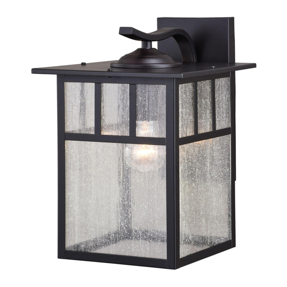
Bulb Type A Max.60W
(not included)
e r
q
i u
e r
m
e
t n
. s
Rubber Pad (H)
Fixture
Set Screw
Socket
Rubber Pad (H)
Ball Nut (G)
Ball Nut
Frame
181010
Advertisement

Related Manuals for Vaxcel T0442


Summary of Contents for Vaxcel T0442
- Page 1 ASSEMBLY AND INSTALLATION INSTRUCTIONS T0442 T0443 WARNING: TO AVOID RISK OF ELECTRICAL SHOCK, BE SURE TO SHUT OFF POWER BEFORE INSTALLING OR SERVICING THIS FIXTURE. 2. READ AND SAVE THESE INSTRUCTIONS. Hardware Package (included): Cross Bar (A) Wire Connector (F)
- Page 2 Spare Parts List: Assembly Kit 5971MM (1SET) Cross Bar (A) Mounting Screw (B) Fixture Mounting Green Grounding Screw (D) Screw (C) Rubber Pad (H) T0442 T0443 Ball Nut (G) Wire Connector (F) Glass (4 PCS) Glass (4 PCS) 10017CS 10018CS T0442 T0443 A:9"...