
Related Manuals for Siemens FDM221


Summary of Contents for Siemens FDM221
- Page 1 FDM221, FDM223, FDM224, FDM223H, FDM224H Manual call points Technical manual Building Technologies Fire Safety & Security Products...
- Page 2 Data and design subject to change without notice. / Supply subject to availability. Sous réserve de modifications techniques et de la disponibilité. © Siemens Switzerland Ltd 2004-2007 We reserve all rights in this document and in the subject thereof. By acceptance of the document the recipient acknowledges these rights and undertakes not to publish the document nor the subject thereof in full or in part, nor to make them available to any third party without our prior express written authorization, nor to use it for any purpose other than for which it was delivered to him.
-
Page 3: Table Of Contents
Symbols and their meaning ..............7 2.1.3 Classification and meaning of additional symbols ........7 Safety-relevant working instructions ............8 Overview ....................9 Setup and function................10 Manual call point FDM221 ..............10 Manual call point FDM223 ..............11 Manual call point FDM224 ..............12 Diagnosis levels ..................13 Accessories.....................14 Project planning ..................15 Installation .....................16... - Page 4 Siemens Building Technologies 007002_e_en_--.doc Fire & Security Products 11.2007...
-
Page 5: About This Document
0BAbout this document About this document Purpose of the document This document contains all information on the manual call points FDM221, FDM223 and FDM224. The consistent observance of the instructions ensures a trouble-free and safe application. Target group This documentation and the instructions contained therein are intended for the... - Page 6 Disregard of the safety regulations Before they are delivered, products are tested to ensure they function correctly when used properly. Siemens disclaims all liability for damage or injuries caused by the incorrect application of the instructions or disregard of warnings of danger contained in the documentation.
-
Page 7: Safety Notes
Safety notes This chapter describes the danger levels and the relevant safety regulations applicable for the use of the products from Siemens Building Technologies. Please read the work instructions as well as the chapter ’About this document’ before beginning any work. -
Page 8: Safety-Relevant Working Instructions
1BSafety notes Safety-relevant working instructions Country-specific standards The products are developed and produced in compliance with the relevant international and European safety standards. Should additional country-specific, local safety standards or regulations concerning project planning, installation, operation and disposal of the product apply in the place of operation, then these standards or regulations must also be taken into account in addition to the safety regulations mentioned in the product documentation. -
Page 9: Overview
2BOverview Overview Manual call point FDM221 Manual call point FDM223 Manual call point FDM224 Housing FDMH291-x Housing FDMH293-x Housing FDMH293-x The manual call points consist of a housing and a call point unit. They have the following features: Individual call point addressing... -
Page 10: Setup And Function
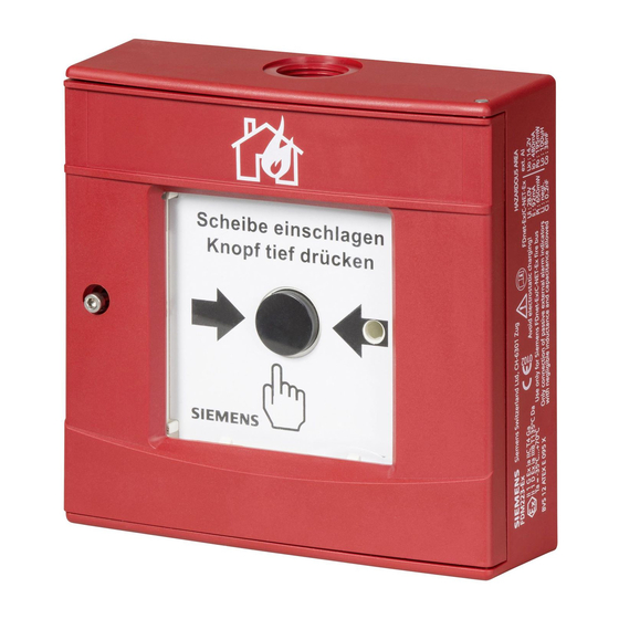
3BSetup and function Setup and function Manual call point FDM221 The manual call point FDM221 triggers alarm when the glass pane is pushed in (direct operation). The alarm is immediately transmitted to the control panel. Legend Housing bottom Switching unit... -
Page 11: Manual Call Point Fdm223
3BSetup and function Manual call point FDM223 The manual call point FDM223 triggers alarm when the glass pane is pushed in and the alarm button is pressed (indirect operation). The alarm is immediately transmitted to the control panel. Legend Housing bottom Switching unit Terminals Stopping lever... -
Page 12: Manual Call Point Fdm224
3BSetup and function Manual call point FDM224 The manual call point FDM224 triggers alarm when the glass pane is pushed in (direct operation). The alarm is immediately transmitted to the control panel. To reset the manual call point FDM224 after an alarm, a new glass pane must be inserted. -
Page 13: Diagnosis Levels
3BSetup and function Diagnosis levels The detector largely auto-monitors its function. The following diagnosis levels are derived from the different control measurings: Normal Exchange required Fault Details see table below. When a fatal error occurs, which makes the proper function of the detector impossible, a fault message is signalled. -
Page 14: Accessories
DMZ1197-AC Protective cover Protection against unintended alarm activation with FDM223 and FDM224 FDMC291 Protective cover Protection against unintended alarm activation with FDM221 Cable gripper Cable gripper with 2 – cable entries max. cable diameter 7.8 – for FDM223 or FDM224 –... -
Page 15: Project Planning
4BProject planning Project planning Compatibility Compatible with all control panel types that support the FDnet detector line. Refer to 'List of compatibility' (doc. no. 008331) for details. Range of application The manual call points are intended for use in places where a fire can be detected by people who can manually trigger an alarm. -
Page 16: Installation
Preparation Depending on the cabling (recessed or surface cabling), the housing must be prepared for inserting the cables. FDM221 1. Break out the key from the housing cover. 2. Press the two key knobs into the recesses (see figure below). -
Page 17: Installation
Installation 6.2.1 Fixation FDM221 1. Install the housing at a height of 1.3 … 1.6 m on an even surface. 2. Pull the cables through the entry opening(s) into the housing. 3. For surface mounting, use screwed cable glands (max. M20 with nut). -
Page 18: Inserting The Protective Cover
When a protective cover is used, proceed as follows: 1. Open the housing. 2. Place the protective cover (1) in the lid (2) (see figure below). 3. Close the housing (3) with the lid (2). FDM221 FDM223/FDM224 007002_e_en_--.doc Fire Safety & Security Products... -
Page 19: Electric Connection
As long as a manual call point is out of service, it must be provided with a Caution note "OUT OF SERVICE“! Only one wire may be connected to each terminal point; only this way is it possible to guarantee a faultless connection over the complete life cycle. Connection diagrams FDM221 FDM223/FDM224 FDnet FDnet FDnet FDnet FDM221 1. - Page 20 5BInstallation FDM223/FDM224 1. Connect the feeding line to the terminals in the call point unit (1), in accordance with the connection diagram. 2. When inserting the call point unit (1) into the housing (2), pay attention to the feeding line. 3.
-
Page 21: Commissioning
Localization red, flashing Performance check FDM221 1. Set the detector line to Test. 2. Insert the key from below into the housing. The glass pane falls down, actuating the switch. The LED flashes. 3. Pull off the key. The glass is pushed back into its initial position and the detector is again ready for operation. - Page 22 6BCommissioning FDM224 1. Set the detector line to Test. 2. Pull the cover of the keyhole to the right. 3. Open the door with the key. The alarm signal is transmitted. 4. Close the door of the detector. The detector is ready for operation again. 5.
-
Page 23: Maintenance / Troubleshooting
After alarm activation the manual call point must be set in operational availability again. This procedure is different for each of the two detector types. FDM221 To set the detector back to operational availability, proceed as follows: 1. Open the housing. - Page 24 7BMaintenance / Troubleshooting FDM223 To set the detector back to operational availability, proceed as follows: 1. Open the housing. 2. Remove the glass pane. 3. Insert a new glass pane. 4. Push the black locking lever (2) in the upper right corner to the right until you hear it clicking.
-
Page 25: Replacing The Glass Pane
7BMaintenance / Troubleshooting Replacing the glass pane FDM221 The glass pane is provided with a number. It is covered by a foil layer. This foil holds the glass splinters together when the glass pane is pushed in, enabling trouble-free removal of the glass. - Page 26 7BMaintenance / Troubleshooting FDM223/FDM224 The glass pane is square-shaped and can be inserted in any direction. Proceed as follows: 1. Pull the cover of the keyhole to the right. 2. Open the housing with the key enclosed in the delivery. Keep the key in a safe place.
-
Page 27: Spare Parts
Spare parts Designation FDM221 FDM223/FDM224 Application Cover with key FDMK291 — To open the housing and for the performance check of FDM221. — DMZ1195 Glass pane FDMG291 DMZ1196-AC A part of the actuation mechanism, protects the switch from soiling. 007002_e_en_--.doc Fire Safety &... -
Page 28: Specifications
8BSpecifications Specifications Technical data Operating voltage 12 … 33 VDC Detector line 200 μA Operating current (quiescent) Maximum current connection factor Quiescent current connection factor Address connection factor Separator connector factor Protocol FDnet System compatibility see doc. no. 008331 'List of compatibility'. Line voltage: Line separator nominal... - Page 29 8BSpecifications Operating temperature -25 … +70 °C Ambient conditions Storage temperature -30 … +75 °C Air humidity ≤95 % rel. Protection category EN60529/IEC529: FDM221, housing FDMH291-x IP44 – FDM223/FDM224, IP44 – housing FDMH293-x without sealing DMZ1197-AD FDM223/FDM224 IP65 – housing FDMH293-x...
-
Page 30: Dimensional Drawings
8BSpecifications Dimensional drawings 9.2.1 Dimensions FDM221, housing FDMH291-x FDM223/FDM224, housing FDMH293-x 9.2.2 Master gauge for recesses FDM221, housing FDMH291-x FDM223/FDM224, housing FDMH293-x Environmental compatibility Electronic components and synthetic materials can be separated. The synthetic material parts are identified and can be disposed of accordingly. - Page 31 8BSpecifications 007002_e_en_--.doc Fire Safety & Security Products 11.2007...
- Page 32 Siemens Switzerland Ltd © Siemens Switzerland Ltd 2004-2007 Building Technologies Group Data and design subject to change without notice. International Headquarters Supply subject to availability. Gubelstrasse 22 CH-6301 Zug Tel. +41 41 - 724 24 24 Fax +41 41 - 724 35 22 www.siemens.com/buildingtechnologies...
Need help?
Do you have a question about the FDM221 and is the answer not in the manual?
Questions and answers