Sign In
Upload
Download
Table of Contents
Contents
Add to my manuals
Delete from my manuals
Share
URL of this page:
HTML Link:
Bookmark this page
Add
Manual will be automatically added to "My Manuals"
Print this page
×
Bookmark added
×
Added to my manuals
Manuals
Brands
Siemens Manuals
Security System
FDM221
Technical manual
Siemens FDM221 Technical Manual
Manual call point
Hide thumbs
Also See for FDM221
:
Technical manual
(32 pages)
1
2
Table Of Contents
3
4
5
6
7
8
9
10
11
12
13
14
15
16
17
18
19
20
21
22
23
24
25
26
27
28
29
30
31
32
33
34
35
36
37
38
39
40
41
42
43
44
45
46
47
48
49
50
51
52
53
54
55
56
57
58
59
60
61
62
page
of
62
Go
/
62
Contents
Table of Contents
Bookmarks
Table of Contents
Table of Contents
1 About this Document
Date Format
Applicable Documents
Download Center
Technical Terms
History of Changes
2 Safety
Safety Instructions
Safety Regulations for the Method of Operation
Standards and Directives Complied with
Release Notes
3 Setup and Function
Overview
Details for Ordering
Product Version es
Setup
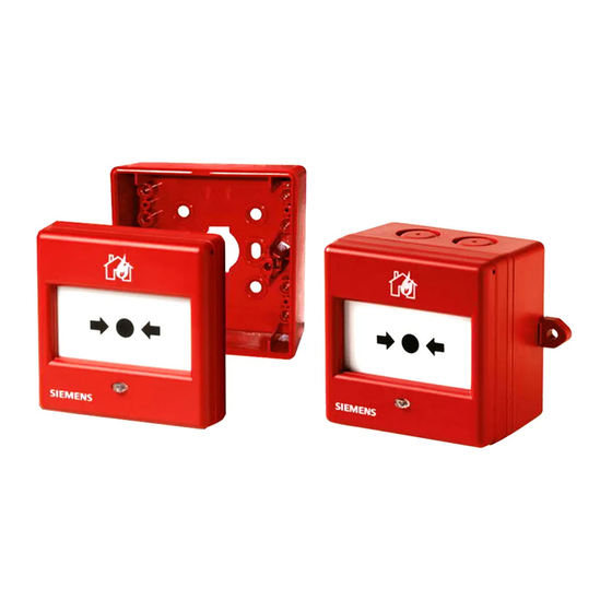
Manual Call Point FDM221
Manual Call Point FDM225
Manual Call Point FDM226
Connections
Indication Elements
Function
Danger Levels
Internal Alarm Indicator
Line Separator
Test Mode
Interface to Service Devices
Diagnosis Levels
Behavior in Degraded Mode
Line Tester
Accessories
Back Box FDMH295-R
Back Box FDMH295-S
Cover with Key FDMK291
Protective Cover FDMC295
Protective Cover FDMC291
Glass Insert FDMG291
Glass Inserts FDMG295-X
Plastic Inserts FDMP295-X
Key FDMK295
Connection Terminal DBZ1190-AB
M20 X 1.5 Metal Cable Gland
M20 X 1.5 Metal Counter Nut
4 Project Planning
Compatibility
Fields of Application
Mounting Site
Environmental Influences
5 Mounting / Installation
Preparation
Installation
Installation
Installing the Protective Cover
6 Commissioning
Localization and Device Testing
Checking Function
7 Maintenance / Repair
Resetting after an Alarm
Status Query
Performance Check
Replacing the Glass Insert or Plastic Insert
8 Specifications
Technical Data
Dimensions
Environmental Compatibility and Disposal
Master Gauges for Holes
Index
Advertisement
Quick Links
1
Manual Call Point Fdm221
2
Manual Call Point Fdm225
3
Connections
4
Mounting / Installation
5
Installation
Download this manual
FDM221, FDM225, FDM226
Manual call point
Technical Manual
009757_f_en_--
2016-08-23
Building Technologies
Control Products and Systems
Table of
Contents
Previous
Page
Next
Page
1
2
3
4
5
Advertisement
Table of Contents
Need help?
Do you have a question about the FDM221 and is the answer not in the manual?
Ask a question
Questions and answers
Related Manuals for Siemens FDM221
Security System Siemens FDM221 Technical Manual
Call points (32 pages)
Security System Siemens FDM225 Series Manual
Call point (8 pages)
Security System Siemens FDM225 Series Installation Manual
Manual call point (8 pages)
Industrial Equipment Siemens FDM225 Series Installation Manual
Manual call point (6 pages)
Security System Siemens FDM225 Technical Manual
Manual call point (62 pages)
Security System Siemens FDM223-Ex Technical Manual
Manual call point (42 pages)
Security System Siemens FDM231-RP Installation Manual
Manual call point (8 pages)
Security System Siemens FDMH293 Series Installation Manual
Back box for manual call point / switching unit (8 pages)
Security System Siemens FDM275 Mounting Manual
Radio manual call point (18 pages)
Security System Siemens FDM275 Technical Manual
Radio manual call point (46 pages)
Security System Siemens FDM273-O Mounting
Radio manual call point (18 pages)
Security System Siemens FDM273 Manual
Radio call point (18 pages)
Security System Siemens FDM273 Mounting
Radio manual call point (20 pages)
Security System Siemens FDM1101-R Series Technical Manual
Manual call point collective (32 pages)
Security System Siemens FDS229-A Technical Manual
Fds229 series. alarm sounder with supplementary optical indication (48 pages)
Security System Siemens FDAI92-Ex Installation Manual
Alarm indicators, adapter frame, surface-mounted housing, indicator housing, incl. washer (8 pages)
This manual is also suitable for:
Fdm226
Fdm225
Table of Contents
Save PDF
Print
Rename the bookmark
Delete bookmark?
Delete from my manuals?
Login
Sign In
OR
Sign in with Facebook
Sign in with Google
Upload manual
Upload from disk
Upload from URL


Need help?
Do you have a question about the FDM221 and is the answer not in the manual?
Questions and answers