
Related Manuals for Siemens FDM223-Ex


Summary of Contents for Siemens FDM223-Ex
- Page 1 FDM223-Ex Manual call point Technical Manual Building Technologies A6V10349616_i_en_-- 2019-01-18 Control Products and Systems...
- Page 2 Issued by: Siemens Switzerland Ltd. Building Technologies Division International Headquarters Theilerstrasse 1a CH-6300 Zug Tel. +41 58 724-2424 www.siemens.com/buildingtechnologies Edition: 2019-01-18 Document ID: A6V10349616_i_en_-- © Siemens Switzerland Ltd, 2012 2 | 42 Building Technologies A6V10349616_i_en_-- Fire Safety 2019-01-18...
-
Page 3: Table Of Contents
Overview ....................17 3.1.1 Details for ordering ..............17 3.1.2 Reference to technical manual ............17 3.1.3 Product version ES ..............18 Setup ......................19 3.2.1 Manual call point FDM223-Ex .............19 3.2.2 Connections ................20 3.2.3 Indication elements ..............20 Function ....................21 3.3.1 Danger levels ................21 3.3.2 Internal alarm indicator ..............21... - Page 4 Commissioning ...................32 Localization and device testing ..............32 Checking function ..................33 Maintenance / troubleshooting ..............34 Resetting after an alarm................34 Status query ....................34 Performance check ..................34 Replacing the glass insert ................35 Specifications ..................36 Technical data ................... 36 Dimensions ....................
-
Page 5: About This Document
Should you require another copy of this document, please contact the Customer Support Center, phone +49 89 9221-8000. Goal and purpose This document contains all information on the manual call point FDM223-Ex. Following the instructions consistently will ensure that the product can be used safely and without any problems. - Page 6 On an FDnet-Ex/C-NET-Ex detector line in a fire detection installation FS20/FS720 ● On the detector line the manual call point FDM223-Ex must be installed downstream of a line adapter (Ex) approved in accordance with national and international regulations. For the FDnet-Ex/C-NET-Ex detector line, this is line adapter (Ex) FDCL221-Ex.
- Page 7 About this document Applicable documents Target groups The information in this document is intended for the following target groups: Target group Activity Qualification Product Manager ● Is responsible for information ● Has obtained suitable specialist passing between the manufacturer training for the function and for the and regional company.
- Page 8 About this document Applicable documents Document identification The document ID is structured as follows: ID code Examples ID_ModificationIndex_Language_COUNTRY A6V10215123_a_de_DE -- = multilingual or international A6V10215123_a_en_-- A6V10315123_a_--_-- Date format The date format in the document corresponds to the recommendation of international standard ISO 8601 (format YYYY-MM-DD). Conventions for text marking Markups Special markups are shown in this document as follows:...
-
Page 9: Applicable Documents
A6V10333771 Technical Manual Line adapter (Ex) FDCL221-Ex A6V10349347 Data sheet Manual call point FDM223-Ex A6V10349619 Installation Manual call point FDM223-Ex Please also observe the documentation for your fire detection system. 1.2 Download center... -
Page 10: Technical Terms, Abbreviations, And Formula Symbols
About this document Technical terms, abbreviations, and formula symbols 1.3 Technical terms, abbreviations, and formula symbols Term Explanation Alarm indicator Advanced Signal Analysis BetrSichV Betriebssicherheitsverordnung, national implementation in the Federal Republic of Germany of Directive 2009/104/EC on the use of work equipment Product version FDnet/C-NET Addressed detector line... -
Page 11: Revision History
About this document Revision history 1.4 Revision history The reference document's version applies to all languages into which the reference document is translated. The first edition of a language version or a country variant may, for example, be version 'd' instead of 'a' if the reference document is already this version. The table below shows this document's revision history: Version Edition date... -
Page 12: Safety
Safety Safety instructions 2 Safety WARNING Contradictory safety instructions Risk of explosion caused by disregarding safety instructions ● Should safety instructions relating to explosion protection contradict other safety instructions, please observe the safety instructions relating to explosion protection. 2.1 Safety instructions The safety notices must be observed in order to protect people and property. - Page 13 Safety Safety instructions Signal word The signal word classifies the danger as defined in the following table: Signal word Danger level DANGER 'DANGER' identifies a dangerous situation, which will result directly in death or serious injury if you do not avoid this situation. 'WARNING' identifies a dangerous situation, which may result in death or serious WARNING injury if you do not avoid this situation.
-
Page 14: Safety Regulations For The Method Of Operation
2.2 Safety regulations for the method of operation National standards, regulations and legislation Siemens products are developed and produced in compliance with the relevant European and international safety standards. Should additional national or local safety standards or legislation concerning the planning, mounting, installation,... - Page 15 Disregard of the safety regulations Before they are delivered, Siemens products are tested to ensure they function correctly when used properly. Siemens disclaims all liability for damage or injuries caused by the incorrect application of the instructions or the disregard of danger warnings contained in the documentation.
-
Page 16: Standards And Directives Complied With
We are grateful for any suggestions for improvement. 2.3 Standards and directives complied with A list of the standards and directives complied with is available from your Siemens contact. 2.4 Release Notes Limitations to the configuration or use of devices in a fire detection installation with a particular firmware version are possible. -
Page 17: Structure And Function
Can be addressed on the FDnet-Ex/C-NET-Ex detector line Area not at risk Ex area FDCL221-Ex FDnet/C-NET FDnet-Ex/C-NET-Ex FC20xx/FC72x Figure 1: Use of a manual call point FDM223-Ex on the FDnet-Ex downstream of a line adapter (Ex) FDCL221-Ex 3.1.1 Details for ordering Type Order number Designation FDM223-Ex... -
Page 18: Product Version Es
Structure and function Overview 3.1.3 Product version ES The product version ES provides the technical status of a device in terms of software and hardware. The product version is provided as a two-digit number. You will find the details of your device's product version: ●... -
Page 19: Setup
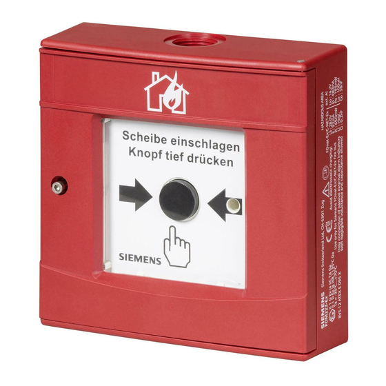
Setup 3.2 Setup 3.2.1 Manual call point FDM223-Ex The FDM223-Ex manual call point triggers an alarm when the glass insert is pushed in and the alarm button is pressed (indirect activation). The alarm is immediately transmitted to the control panel. -
Page 20: Connections
Structure and function Setup 3.2.2 Connections The manual call point FDM223-Ex has six spring clips on the top of the switching unit; these are for the detector line and for connecting external alarm indicators. Figure 5: Switching unit with spring clips 3.2.3 Indication elements... -
Page 21: Function
Structure and function Function 3.3 Function 3.3.1 Danger levels The manual call point can transmit the following danger levels to the control panel: Danger level Meaning Normal state, no danger Alarm The evaluation of the danger level and the resulting measures (e.g. activation of remote transmission) are configured on the control panel. -
Page 22: Behavior In Degraded Mode
Structure and function Function 3.3.5 Behavior in degraded mode For the FDnet/C-NET and a FDnet-Ex/C-NET-Ex connected to the FDnet/C-NET, the following applies: When the main processor of the fire control panel fails, the control panel is in degraded mode operation. Depending on the control panel type, the fire control panel can continue to perform the most important alarming and signaling functions in degraded mode operation. -
Page 23: Accessories
For introducing a cable into the following devices: – Base attachment humid FDB293 – Base attachment wet FDB295 – Manual call point FDM223-Ex ● For cable diameters of 3.5…5.5 mm ● Temperature range: -40…+100 °C ● Allows for increased IP protection ●... -
Page 24: Seal Dmz1197-Ad
Structure and function Accessories 3.4.4 Seal DMZ1197-AD ● For using the manual call point in areas where there is a risk of splash water ● Increases the IP protection category of the manual call point ● Order number: BPZ:5470680001 3.4.5 Line adapter (Ex) FDCL221-Ex ●... -
Page 25: Planning
Planning Compatibility 4 Planning Please always take the country-specific provisions and the alarm organization for project planning into account. In addition, the connection factors stated in the specifications must also be taken into account. 4.1 Compatibility Compatible with control panels that support the FDnet-Ex/C-NET-Ex detector line. The table below shows the compatibility of the manual call point with various control panels: Detector line... -
Page 26: Mounting/Installation
(Ex) FDCL221-Ex. 5.1 Preparation In the case of the manual call point FDM223-Ex, cables cannot be inserted through the back of the housing. Cables must enter through one of the cable entry openings provided in the housing. -
Page 27: Mounting
5.2 Mounting Observe the country-specific regulations for the exact mounting height! w The manual call point FDM223-Ex is prepared for installation. See the chapter 'Preparation [➙ 26]'. 1. Secure the housing at a height of 0.9…1.6 m on an even surface. -
Page 28: Electrical Connection
Mounting/Installation Electrical connection 5.3 Electrical connection Notes on work on electrical installations WARNING Deactivating the manual call points prevents alarms from being forwarded. The alarm is not triggered. ● Mark deactivated manual call points or those which are not fully functional with the notice 'NOT IN USE'! NOT IN USE AUSSER BETRIEB... - Page 29 Mounting/Installation Electrical connection Connection diagram LINE LINE Ext. AI Figure 10: Connection diagram for manual call point FDM223-Ex Connecting the manual call point FDM223-Ex Figure 11: Installation of manual call point FDM223-Ex Screw Housing Switching unit Glass insert Screw Seal DMZ1197-AD (accessories)
- Page 30 Mounting/Installation Electrical connection WARNING Incorrect connection of detector line cable shielding Risk of explosion ● Never connect detector line cable shieldings in an area at risk of explosion with detector line cable shieldings in an area not at risk of explosion ●...
-
Page 31: Installing The Protective Cover
5. Install the glass insert. See the chapter 'Replacing the glass insert [➙ 35]'. 6. Close the door of the manual call point. a The protective cover is inserted. Figure 12: Installing protective cover DMZ1197-AC on a manual call point FDM223-Ex Protective cover DMZ1197-AC Pivot pin... -
Page 32: Commissioning
Commissioning Localization and device testing 6 Commissioning The device is commissioned via the control panel. The exact procedure is described in the control panel documentation. Conduct a performance check once commissioning is complete. 6.1 Localization and device testing The manual call points have an internal alarm indicator. This alarm indicator may as well be activated from the control panel for localization and device testing. -
Page 33: Checking Function
The manual call point is ready for operation again. 7. Set the detector line to 'Normal operation' on the control panel. a The detector line is ready for operation again. Figure 13: Resetting manual call point FDM223-Ex Locking lever 33 | 42... -
Page 34: Maintenance / Troubleshooting
Maintenance / troubleshooting Resetting after an alarm 7 Maintenance / troubleshooting 7.1 Resetting after an alarm After an alarm is activated, the manual call point must be reset to a state in which it is ready for operation. Reset the detector to a state of operational readiness as follows: w The glass insert has been shattered and the alarm button is pressed. -
Page 35: Replacing The Glass Insert
Maintenance / troubleshooting Replacing the glass insert 7.4 Replacing the glass insert The glass insert is square-shaped and can be inserted in any direction. CAUTION Risk of cutting injuries when removing the glass fragments Remove the glass fragments carefully To replace the glass insert, proceed as follows: w The door of the manual call point is open. -
Page 36: Specifications
Specifications Technical data 8 Specifications 8.1 Technical data Device labeling IECEx Scheme: Ex ia IIC T4 Ga, Ta = -35…70 °C Ex ia IIIB T135 °C Da , Ta = -35…70 °C Directive 2014/34/EU: II 1 G Ex ia IIC T4 Ga, Ta = -35…70 °C (ATEX directive) II 1 D Ex ia IIIB T135 °C Da, Ta = -35…70 °C Ex-related connection... - Page 37 Specifications Technical data External alarm indicators Number of external alarm indicators Max. 1 external alarm indicator FDAI9x-Ex that can be connected Voltage DC 9…14.2 V Current 9…15 mA Length of line ● Max. 30 m with unshielded cables, or when the shielding is connected to the positive pole of the detector base ●...
-
Page 38: Dimensions
Specifications Dimensions 8.2 Dimensions 134.3 42.5 8.3 Master gauge for recesses 10.65 123.65 116.65 18.15 A = Ø 4.8 38 | 42 Building Technologies A6V10349616_i_en_-- Fire Safety 2019-01-18... -
Page 39: Environmental Compatibility And Disposal
Specifications Environmental compatibility and disposal 8.4 Environmental compatibility and disposal This equipment is manufactured using materials and procedures which comply with current environmental protection standards as best as possible. More specifically, the following measures have been undertaken: ● Use of reusable materials ●... -
Page 40: Glossary
Glossary Glossary Associated electrical equipment Electrical equipment that contains both energy-limited and non-energy-limited circuits, and is structured in such a way that the non-energy-limited circuits cannot have a negative effect on any of the energy-limited circuits. Qualified person A qualified person is someone who, as a result of their professional training and current occupational activities, has the knowledge required to test the work equipment. -
Page 41: Index
Index Index Installation in wet areas ........27 Alarm indicator ........... 21, 32 Intended use ............. 6 Approvals ............36 Internal alarm indicator ........ 21, 32 Internet ............5 CE marking ............. 36 Collective behavior List of compatibility ........22, 25 Degraded mode operation....... - Page 42 Issued by © Siemens Switzerland Ltd, 2012 Siemens Switzerland Ltd Technical specifications and availability subject to change without notice. Building Technologies Division International Headquarters Theilerstrasse 1a CH-6300 Zug +41 58 724 2424 www.siemens.com/buildingtechnologies Document ID: A6V10349616_i_en_-- Edition: 2019-01-18...
Need help?
Do you have a question about the FDM223-Ex and is the answer not in the manual?
Questions and answers