Siemens FDM225 Technical Manual
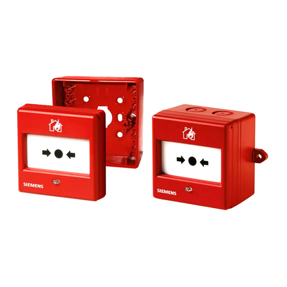
Manual call point
Hide thumbs
Also See for FDM225:
- Installation manual (8 pages) ,
- Installation manual (6 pages) ,
- Manual (8 pages)

Related Manuals for Siemens FDM225


Summarization of Contents
About This Document
1.1 Applicable Documents
Lists related documents for further reference.
1.2 Download Center
Provides instructions and links for downloading technical documents.
1.3 Technical Terms
Defines key terminology used throughout the manual.
1.4 History of Changes
Details the revision history and modifications made to the document.
Safety
2.1 Safety Instructions
Outlines essential safety precautions, symbols, and hazard warnings.
2.2 Safety Regulations for Operation
Specifies safety rules for installation, maintenance, and operation.
2.3 Standards and Directives
Lists the standards and directives the product conforms to.
2.4 Release Notes
Provides information on firmware version limitations and usage.
Setup and Function
3.1 Overview
Introduces manual call points and their general features.
3.1.1 Details for Ordering
Lists product types, order numbers, and designations for call points.
3.1.2 Product Version ES
Explains how to identify the product version on labels and plates.
3.2 Setup
Provides step-by-step instructions for setting up manual call points.
3.2.1 FDM221 Setup Procedure
Details the setup procedure for the FDM221 model.
3.2.2 FDM225 Setup Procedure
Details the setup procedure for the FDM225 model.
3.2.3 FDM226 Setup Procedure
Details the setup procedure for the FDM226 model.
3.2.4 Connections
Explains the wiring and connection terminals for the call points.
3.2.5 Indication Elements
Describes the function and meaning of the internal alarm indicator LED.
3.3 Function
Explains the operational functions and indicators of the call points.
3.3.1 Danger Level Transmission
Describes the danger levels transmitted to the control panel.
3.3.2 Internal Alarm Indicator Function
Explains the meaning of LED indications for alarm status.
3.3.3 Line Separator Functionality
Details the function of the integrated line separator for fault isolation.
3.3.4 Test Mode Operation
Explains how to activate and use the test mode for call points.
3.3.5 Service Device Interface
Describes the interface for communication with service devices.
3.3.6 Diagnosis Level Interpretation
Explains the different diagnosis levels and error reporting.
3.3.7 Degraded Mode Operation Behavior
Describes system behavior when the control panel fails.
3.3.8 Line Tester Functionality
Explains the functionality of the line tester for fault detection.
3.4 Accessories
Lists and describes available accessories for the manual call points.
3.4.1 Back Box FDMH295-R
Details specifications of the FDMH295-R back box.
3.4.2 Back Box FDMH295-S
Details specifications of the FDMH295-S back box.
3.4.3 Cover with Key FDMK291
Describes the protective cover with key for access.
3.4.4 Protective Cover FDMC295
Details the protective cover FDMC295 for unintended alarms.
3.4.5 Protective Cover FDMC291
Details the protective cover FDMC291 for unintended alarms.
3.4.6 Glass Insert FDMG291
Describes the glass insert for alarm activation and protection.
3.4.7 Glass Inserts FDMG295-x
Details glass inserts available in country-specific designs.
3.4.8 Plastic Inserts FDMP295-x
Details plastic inserts available in country-specific designs.
3.4.9 Key FDMK295
Describes the key for testing and resetting manual call points.
3.4.10 Connection Terminal DBZ1190-AB
Details the auxiliary terminal for connecting cables.
3.4.11 M20 x 1.5 Metal Cable Gland
Describes the metal cable gland for introducing cables into the housing.
3.4.12 M20 x 1.5 Metal Counter Nut
Describes the metal counter nut for use with cable glands.
Project Planning
4.1 Compatibility
Lists control panel compatibility with detector lines.
4.2 Fields of Application
Specifies where the manual call points are intended for use.
4.3 Mounting Site
Specifies required mounting locations and height.
4.4 Environmental Influences
Outlines environmental factors to consider for device operation.
Mounting / Installation
5.1 Mounting Preparation Steps
Details steps to prepare the housing for cable entry.
5.2 General Installation Procedures
Provides instructions for installing the manual call points.
5.3 Electrical Installation Notes
Covers important notes and precautions for electrical installation work.
5.4 Protective Cover Installation
Details how to attach protective covers to the call points.
Commissioning
6.1 Device Localization and Testing
Explains how to test and locate devices using the alarm indicator.
6.2 Functionality Check Procedure
Provides steps to verify the manual call point's functionality.
Maintenance / Repair
7.1 Resetting After Alarm
Describes the procedure to reset the call point after an alarm.
7.2 Status Query Methods
Explains how to query the status via tester or control panel.
7.3 Performance Check Guidelines
Details how to perform regular performance checks on the devices.
7.4 Replacing Inserts
Provides step-by-step instructions for replacing inserts.
Specifications
8.1 Technical Data Specifications
Lists detailed technical specifications, operating data, and standards.
8.2 Device Dimensions
Provides detailed physical dimensions for each model.
8.3 Environmental Compliance and Disposal
Covers environmental impact and proper disposal methods.
8.4 Mounting Hole Master Gauges
Shows drilling templates for mounting holes.
Need help?
Do you have a question about the FDM225 and is the answer not in the manual?
Questions and answers