Table of Contents
Troubleshooting

Related Manuals for EFI E-35A


Summary of Contents for EFI E-35A
- Page 1 Color Controller E-35A Installation and Service Guide A guide for service technicians Replacement parts and specifications are subject to change. For a current parts list, contact your authorized service/support center.
- Page 2 Imaging, Inc. (“EFI”), except as expressly permitted herein. Information in this documentation is subject to change without notice and does not represent a commitment on the part of EFI. The documentation is further covered by Legal Notices distributed with this product. The documentation may be provided in conjunction with EFI Software (“Software”) and any other EFI product described in the documentation.
-
Page 3: Table Of Contents
Printing E-35A pages from the monitor, keyboard, and mouse ....... . - Page 4 Removing and replacing E-35A internal components ........
- Page 5 When backing up an existing E-35A installation ........
- Page 6 Installation and Service Guide Contents Safety and emissions compliance ................116 Safety approvals .
-
Page 7: List Of Figures
Figure 2: Space requirements for the E-35A without optional furniture ....... - Page 8 Figure 31: Diagram of the E-35A motherboard ........
-
Page 9: Introduction
The E-35A adds computer connectivity and highly efficient PostScript and PCL printing ability to the Pro C7200SL printer. With the E-35A, customers can use the printer as a PostScript printer and scanner. Once it is connected to the printer through the network, customers can print to the E-35A from supported client computers on the network. -
Page 10: Before You Service The E-35A
Installation and Service Guide Introduction Before you service the E-35A Before you service the E-35A, it is strongly recommended that you make sure that you have the required tools (see “Tools you will need” on page 10) and carefully review all precautions (see “Precautions”... - Page 11 Keep magnets and magnetic-sensitive objects away from electronic components, especially the hard disk drive. Avoid fan blades Warning: The E-35A contains hazardous moving parts. When servicing the E-35A, keep away from moving fan blades. Attention : ce produit contient des pièces mobiles dangereuses. Veuillez le maintenir à l'écart des pales de ventilateur lors de sa maintenance.
- Page 12 The power cable Observe the following guidelines: • Only use the power cable that shipped with the E-35A or an appropriate replacement power cable. For replacement parts, see your authorized service support center. • Before you open the E-35A, unplug the E-35A.
- Page 13 Installation and Service Guide Introduction Do not bring liquids near the E-35A If liquid spills on the E-35A, immediately unplug the E-35A. Do not open the power supply For more information about the power supply, see“Power supply” on page 76.
-
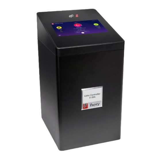
Page 14: Figure 1: E-35A
Lift the E-35A carefully Lift the E-35A by holding the handling grip available at rear side of the E-35A. Caution: Never lift the E-35A by grasping the top panel. The top panel does not support the weight of the E-35A. Figure 1:... -
Page 15: Installing Hardware
About the installation process It is strongly recommended that you review this chapter before you install the E-35A. Also keep in mind that installation problems are easier to avoid and diagnose if you proceed from the component level to the system level, verifying functionality at each step. -
Page 16: Checking The Customer Site
4 Click Save. 5 Click Continue, then click Reboot. Wait until the E-35A reboots and becomes Idle. It may take up to 15 minutes to complete the system language change. To change the E-35A language from Fiery QuickTouch 1 On the Fiery QuickTouch display screen, press the Quick launch icon on the bottom-left corner (seepage 32). -
Page 17: Setting Customer Expectations
Make sure that adequate space is available for the E-35A and the furniture. Allow enough space at the connector panel for the cables to route easily and at the side panel so that the E-35A does not interfere with use of or service to the printer (such as clearing a paper jam). -
Page 18: Unpacking The E-35A
Call the carrier immediately to report the damage and file a claim. Let the customer or site administrator know that in order to take full advantage of the E-35A, the user software must be installed on computers that will print to the E-35A. -
Page 19: Connecting The E-35A
Installation and Service Guide Installing Hardware 6 Locate the EFI/Fiery decal in the shipping container and affix it to the printer as shown. Figure 3: Affixing the decal to the printer EFI/Fiery decal Connecting the E-35A Before you connect the E-35A, it is strongly recommended that you review all “Precautions”... -
Page 20: Figure 4: E-35A Front And Connector Panel
Installation and Service Guide Installing Hardware Figure 4: E-35A front and connector panel Front panel Connector panel Fiery QuickTouch LCD Type A USB2.0 ports (x2) Type A USB 3.0 ports (x3) Network port (upper RJ-45) Reset button Display port Power button Type A USB2.0 ports (x2) -
Page 21: (Optional) Connecting The Monitor, Keyboard, Mouse, And Power
Note: For information about the monitor, keyboard, and mouse, see the documentation that accompanies those products. 1 Make sure that the E-35A is installed in the furniture and the monitor is securely attached to the top of the E-35A. For more information, see the assembly instructions that accompany the furniture. -
Page 22: Figure 5: Straight-Through And Crossover Ethernet Cables
2 Connect the Printer interface (Crossover Ethernet) cable to the correct port on the printer and to the Lower RJ-45 port on the E-35A. Important: The crossover Ethernet cable and the straight-through network cable (included with the E-35A) look similar, but are not interchangeable. Make sure that you connect the straight-through Ethernet cable to the Lower RJ-45 port on the E-35A connector panel. -
Page 23: Figure 6: Printer And E-35A Cable Connection
2 Make sure that the network cable is connected to the customer site network. 3 Connect the network cable to the Upper RJ-45 network port on the back of the E-35A. The E-35A provides twisted pair connectivity to an Ethernet network. When the network cable is connected, the Ethernet interface automatically detects the speed of the network environment. -
Page 24: Starting The E-35A For The First Time
After power on, the site administrator should perform Network Setup, verify the network connection, verify that the E-35A appears in the list of printers, and then print a few test documents from a networked computer that will use the E-35A. For more information, see Configuration and Setup, which is part of the user documentation set. -
Page 25: Configuring A Static Ip Address For The E-35A
Configuring a static IP address for the E-35A If the customer requires the E-35A to be configured with a static IP address (for example, in a non-DHCP network environment), obtain a valid static IP address from the network administrator and configure the E-35A as described in the following procedure. -
Page 26: Enabling The Power Synchronization
3 Locate the USB cable in the accessory kit that comes with the E-35A. 4 Connect one end of the USB cable (Type B) to the port on the printer interface board of the E-35A. Connect the other end of the cable (Type A) to the USB port on the printer. -
Page 27: Figure 9: Usb Connection Between Printer And E-35A
1 Turn off the printer using the main power switch. Wait until the E-35A shuts down. 2 Make sure that the power switch on the connector panel of the E-35A is OFF position (|). 3 Set the switch on the printer interface board to the OFF position. -
Page 28: Completing The Installation
9 Store the output and the current Configuration page(s) near the printer. 10 After the site administrator completes the Setup, use the Fiery System Restore to copy the contents of the E-35A hard disk drive to an image file. For detailed instructions, see “Using Fiery System Restore”... -
Page 29: Using The E-35A
Note: The Fiery NX Station (monitor, mouse, and keyboard) is provided as an optional feature. Fiery Ticker When you log on to the E-35A using the monitor or Remote Desktop Connection, Fiery Ticker automatically starts showing the status bar. Figure 10: Fiery Ticker status bar... -
Page 30: Command Workstation
3 If you printed the E-35A Test Page, examine the quality of the Test Page from the printer. If the Test Page prints, you know the E-35A is functional and the connection between the E-35A and the printer is working. If the Test Page fails to print, look up printing problems in“Table 5: E-35A error messages and conditions”... -
Page 31: Fiery Quicktouch
In the Server menu, click Device Center, select General Info tab and then click Configure in the lower right corner. 2 If the Fiery Setup dialog box displays, click Configure. Fiery QuickTouch The Fiery QuickTouch on the front of the E-35A allows you to do the following: • View print job status and alerts •... -
Page 32: Overview Of Fiery Quicktouch Menu Options
Installation and Service Guide Using the E-35A Figure 11: Fiery QuickTouch panel Fiery QuickTouch LCD Type A USB 3.0 ports (x3) Power button Reset button (requires pin) Overview of Fiery QuickTouch menu options The following options are available from the Fiery QuickTouch main menu: Figure 12: Fiery QuickTouch home screen The Home screen is the main interface for job status, and displays various screen elements. - Page 33 E-35A name and status Number of pages and copies that are printing Tapping the Fiery icon shows more information about the E-35A and the network address. Icon of the print job type Queued jobs list If there are no print jobs being processed, an Idle Tapping the Queue icon shows a list of jobs that are status displays.
-
Page 34: Figure 13: Queue Jobs Window
Installation and Service Guide Using the E-35A Figure 13: Queue Jobs window The Printed jobs list provides job status and details about the jobs that have been printed. Figure 14: Printed Jobs window In either the Queue jobs or Printed jobs screen, you can tap Back to go back to the Home screen. -
Page 35: Quick Launch Menu
Tapping the Home icon takes you back to the Home screen. Before accessing Fiery System Restore or Settings, you must log in as an administrator. For more information on backing up and restoring the E-35A, see“Using Fiery System Restore” on page 88. -
Page 36: Using The Printer Touch Panel
1 Press the Home button on the printer touch panel. 2 From the Home screen of the printer touch panel, select EFI Fiery. If the EFI Fiery icon does not display, move to the other screen by swiping the touch screen until the EFI Fiery icon appears. -
Page 37: Main Tab
Suspend Printing Suspend print activity between the E-35A and the printer. Use this command to interrupt the current E-35A job, for example, to perform maintenance tasks. Jobs continue to process on the E-35A. After you complete maintenance tasks, choose Resume Printing to continue printing jobs from the E-35A. -
Page 38: Fiery Tab
To troubleshoot printer interface board, choose this menu Clear Server Clear all jobs in all server queues, as well as all jobs archived on the E-35A hard disk, the index of archived jobs (in the Archive window), all FreeForm masters, and the index of FreeForm masters (in the FreeForm window). -
Page 39: Printable Info Menu
1 If it is not powered on already, power on the printer and allow it to warm up. 2 If it is not powered on already, power on the E-35A using the power button on the front panel and allow it to start up completely (approximately three minutes). -
Page 40: Using The Fiery Desktop On The Printer Touch Panel
6 If you printed the Test Page, examine the quality of the page. If the Test Page prints, you know the E-35A is functional and the connection between the E-35A and the printer is working. If the Test Page fails to print, look up printing problems in the Troubleshooting table on page 108. -
Page 41: Network Status Leds
Starting, shutting down, restarting, and rebooting Generally, you can leave the E-35A and the printer running all the time. Restarting the E-35A resets the E-35A system software, but does not reboot the entire system. Network access to the E-35A is temporarily interrupted and all currently processing jobs are terminated. -
Page 42: Figure 19: E-35A Power Switch
Click “>>” icon in the Fiery Ticker and select Server Actions > Restart Fiery. Click OK. 4 If you shut down the E-35A, move the E-35A power switch to the off (O) position for maximum energy savings or service (wait 10 seconds before you proceed). - Page 43 1 Make sure that the E-35A is not receiving, processing, or printing any jobs. If Printing appears on the touch panel, the E-35A is processing. You must wait until the system finishes and reaches Idle before restarting or shutting down.
- Page 44 Network access to the E-35A is terminated and all currently processing jobs are aborted and may be lost. Note: Use the reset button on the front of the E-35A only if the system is unresponsive to keyboard or mouse actions. 5 Press OK.
-
Page 45: Replacing Parts
Installation and Service Guide Replacing Parts Replacing Parts Generally, the E-35A requires no regular service or maintenance. Use the procedures in this chapter to inspect, remove, reseat, and replace major hardware components. Overview This chapter includes information about servicing the following components: •... -
Page 46: E-35A Diagrams
Installation and Service Guide Replacing Parts E-35A diagrams The following figures provide an overview of E-35A components. Figure 21: E-35A front and connector panel Front panel Connector panel Fiery QuickTouch LCD Type A USB2.0 ports (x2) Type A USB 3.0 ports (x3) -
Page 47: Figure 22: Exploded View Of E-35A
Installation and Service Guide Replacing Parts Figure 22: Exploded view of E-35A Chassis cover 10-pin power button cable Power supply unit HDD SATA cable DIMM (x2) Chassis Fiery QuickTouch USB cable Fiery QuickTouch power cable Battery HDD bracket CPU cooling assembly... -
Page 48: Figure 23: Cable Connections Inside The E-35A
Installation and Service Guide Replacing Parts Figure 23: Cable connections inside the E-35A Chassis fan Power supply unit CPU fan Cable From Chassis fan cable Chassis fan FRONT FAN connector on motherboard (J30) Fiery QuickTouch USB cable Fiery QuickTouch USB USB 3.0 HDR connector on motherboard (J14) -
Page 49: Accessing Internal Components
Shutting down the system You can shut down the E-35A from the Fiery QuickTouch or printer touch panel. Note: If the power synchronization is set to ON, you can shut down the E-35A by turning off the printer using the main power switch. -
Page 50: Figure 24: Removing The Chassis Cover
Fiery QuickTouch(see page 5 Place the E-35A on a flat surface. Carefully position the E-35A so that it is standing in its normal position. To remove and replace the chassis cover 1 Remove the two screws at the rear right of the chassis. -
Page 51: Figure 25: Replacing The Chassis Cover
Installation and Service Guide Replacing Parts 3 To replace the chassis cover, slide the cover into place and secure with two screws on the rear side of the chassis. Figure 25: Replacing the chassis cover To remove and replace the front panel 1 From inside the chassis, bend outward the four tabs on the front panel and then lift the front panel away from the chassis. -
Page 52: Fiery Quicktouch Display Module
Caution: It is highly recommended that you use a screwdriver with a magnetic tip when removing or replacing the screws used to attach the Fiery QuickTouch. If you do not, the screws you remove or replace might fall inside the E-35A. -
Page 53: Figure 27: Removing Fiery Quicktouch Connectors
Installation and Service Guide Replacing Parts To remove the Fiery QuickTouch 1 Remove the chassis cover (See page 50). 2 Remove the two connectors attached to the Fiery QuickTouch. Figure 27: Removing Fiery QuickTouch connectors Power harness USB connector Support bracket Screw, bracket Tie-wrap a Remove the power harness by unplugging it. -
Page 54: Figure 28: Removing/Replacing The Fiery Quicktouch
Installation and Service Guide Replacing Parts d Remove the screw holding the bracket to the Fiery QuickTouch. Caution: Use a screwdriver with a magnetic tip so you do not drop the screw into the Color Controller E- 35A. Figure 28: Removing/replacing the Fiery QuickTouch Fiery QuickTouch Screws, rear side (x2) Screw, front side... -
Page 55: Removing And Replacing E-35A Internal Components
5 Insert the screw which holds the metal connector to the Fiery QuickTouch and tight it to secure the Fiery QuickTouch. Caution: Use a screwdriver with a magnetic tip so you do not drop a loose screw into the E-35A. 6 Insert the front screw and tight it to secure the front portion of the Fiery QuickTouch 7 Insert the two rear screws and tight them to secure the rear portion of the Fiery QuickTouch. -
Page 56: Printer Interface Board
The printer interface board provides the print interface between the E-35A and the printer. The printer interface board processes the image data and sends it to the printer through the printer interface cable available on the E-35A connector panel. It is installed in PCIE x16 slot on the motherboard. -
Page 57: Motherboard
The CPU mounted on the motherboard controls the image data transferred to and from the printer interface board. The motherboard also controls hard disk drive functions and the communication between the E-35A and external devices. -
Page 58: Motherboard Replacement Overview
Installation and Service Guide Replacing Parts Motherboard replacement overview You suspect a faulty motherboard or hard disk drive. Note: Each page reference includes more information for each task. page 81 Replace the hard disk drive. page 96 Reinstall system software. Yes. -
Page 59: Removing The Motherboard
Installation and Service Guide Replacing Parts Figure 31: Diagram of the E-35A motherboard Type A USB2.0 ports (x2) / Network cable FRONT FAN connector (J30) Battery (CR1) port (Upper RJ-45) 4-pin power connector (PWRCONN1) Type A USB2.0 connector (x2) HDD data connector (SATA0) - Page 60 Important: Follow standard ESD precautions while handling the motherboard and all components. For details, see“Precautions” on page 10. To remove motherboard components from the motherboard 1 Access and open the E-35A (see page 49). 2 Remove the printer interface board (see page 56).
-
Page 61: Replacing The Motherboard
Replacing the motherboard Use the following procedure to replace the motherboard in the E-35A chassis. Failure to follow the instructions in this section may corrupt the system (not easily repaired in the field) or result in an incomplete installation. - Page 62 • First, replace the hard disk drive and install system software. Always replace a faulty hard disk drive with a new hard disk drive. Transferring a hard disk drive from one E-35A to another is incorrect and strongly discouraged. •...
- Page 63 Important: Do not transfer the BIOS chip from the old motherboard onto the new motherboard. Doing so can damage the E-35A. BIOS chips are not interchangeable. 2 Install the motherboard in the chassis. Angle the motherboard so that the connectors on the motherboard fit into the cutouts in the connector panel of...
-
Page 64: Verifying New Motherboard Installation, And Transferring Options And Bios Information
Important: Make sure that unused connector panel slots are covered with slot covers. Uncovered slots reduce air flow and may cause the E-35A to overheat. 4 If you reinstall the old motherboard, reassemble the E-35A and verify its functionality (see page 82). - Page 65 Enter on the keyboard. Type Fiery.1, the password is case-sensitive; for example, fiery.1 will not work. At this point the E-35A is in Service Mode, so you can verify that the new motherboard solves the problem that you are trying to troubleshoot. Service Mode is not indicated on the monitor or on the Fiery QuickTouch screen.
- Page 66 To transfer options and BIOS information to the new motherboard Note: This procedure, which takes approximately 15-20 minutes, assumes that the E-35A is fully assembled with the new motherboard, and verified in Service Mode (see page 65).
-
Page 67: Dimm
Installation and Service Guide Replacing Parts DIMM DIMM (dual in-line memory module) is held in place by a lever at the end of a DIMM slot. The E-35A motherboard contains two DIMM slots (DIMM-A0 and DIMM-B0, see Figure 31 on page 59). Use the DIMM-A0 slot to install the first DIMM and DIMM-B0 slot to install the second DIMM. -
Page 68: Cpu And Cpu Cooling Assembly
Installation and Service Guide Replacing Parts CPU and CPU cooling assembly The CPU is installed in a socket on the motherboard. Before removing the CPU from its socket, remove the motherboard from the chassis (see page 61), disconnect the CPU fan cable from the motherboard, and remove the cooling assembly from the CPU socket (see page 69). -
Page 69: Figure 34: Removing The Cpu Cooling Assembly
Installation and Service Guide Replacing Parts To remove a CPU 1 Access and open the E-35A (see page 49). 2 Remove the motherboard components (see page 60). 3 Remove the motherboard from the chassis (see page 61). Place the motherboard on a flat, antistatic surface. -
Page 70: Figure 35: Removing/Replacing The Cpu
Installation and Service Guide Replacing Parts 7 Open the load plate (see Figure 35). Figure 35: Removing/replacing the CPU Yellow triangle Flat corner of socket border Socket lever in the open position Load plate open 8 Grasp the CPU by its edges, lift it out of the socket, and then place the CPU in a safe place. Note: If you remove the CPU from the motherboard to install it on a new motherboard, unpack the new motherboard and remove the protective plastic cover from the CPU socket. - Page 71 9 Install the motherboard in the chassis (see page 63). 10 Replace the motherboard components (see page 64). 11 Reassemble the E-35A and verify its functionality (see page 82). 12 If you installed a new CPU, configure the time and date in Setup (see page 73).
-
Page 72: Motherboard Battery
Installation and Service Guide Replacing Parts Motherboard battery The battery is located in CR1 socket on the motherboard. Spare batteries are not provided by your authorized service/ support center. If you must replace the battery, use a 3V manganese dioxide lithium coin cell battery (Panasonic CR2032 or equivalent). -
Page 73: Figure 36: Motherboard Battery
1 On a client computer that is connected to the same network as the E-35A, open a Web browser window. 2 In the URL field of the browser, type the IP address or DNS name of the E-35A, and press Enter. -
Page 74: Motherboard Jumpers
A fan mounted inside the E-35A chassis draws air into the E-35A to cool components. The fan runs continuously when the system is on. You should hear the fan start as soon as you power on the E-35A. If you do not hear the fan, there may be a faulty power connection. -
Page 75: Figure 37: Removing/Replacing The Chassis Fan
Installation and Service Guide Replacing Parts Figure 37: Removing/replacing the chassis fan Chassis fan Rivets (x4) Airflow direction 4 Remove the fan from the chassis. To replace the chassis fan 1 Position the fan against the chassis. An arrow on the side of the chassis fan indicates the airflow direction. Make sure that the chassis fan is positioned with the label against the chassis. -
Page 76: Power Supply
Installation and Service Guide Replacing Parts Power supply This section describes how to remove and replace the E-35A power supply. For more information about the power supply, see “Specifications” on page 116. Caution: Do not open the power supply for service or troubleshooting. Opening the power supply will void the warranty. -
Page 77: Figure 38: Removing The Power Supply
Installation and Service Guide Replacing Parts 7 Lift the power supply out of the chassis, taking care to gather the power supply cables. Figure 38: Removing the power supply Power supply cables Power switch Power supply unit Screws (x4) To replace the power supply 1 Place the power supply inside the chassis (see Figure 38). -
Page 78: Hard Disk Drive (Hdd)
7 Secure the power cables to the chassis using the two plastic clips on the base of the chassis. 8 Replace any tie-wraps that you may have removed or cut while removing the power cables earlier. 9 Reassemble the E-35A and verify its functionality (see page 82). - Page 79 The appropriate system software and documentation for the E-35A that you are servicing. • A compatible version of the user software for the networked computers that will print to the E-35A. To remove the HDD 1 If you are replacing the HDD with a new HDD, allow the site administrator the opportunity to print the Job Log and save any custom simulation and output profiles.
-
Page 80: Figure 39: Removing The Hdd Assembly
Installation and Service Guide Replacing Parts 6 Carefully lift the HDD assembly to release its lower edge from the mounting posts in the chassis, and then remove the HDD assembly from the chassis. Figure 39: Removing the HDD assembly HDD assembly Screws, HDD bracket (x2) 7 If you are replacing the HDD with a new HDD, remove the HDD from its bracket. -
Page 81: Figure 40: Removing The Hdd Bracket
Installation and Service Guide Replacing Parts Figure 40: Removing the HDD bracket HDD bracket Screws, HDD bracket (x4) 8 Place the HDD in an antistatic bag. Replacement HDD is shipped without any pre-installed system software. After installing a HDD, you must install the appropriate system software. -
Page 82: Restoring And Verifying Functionality After Service
Replacing Parts 8 Reassemble the E-35A (see page 82). 9 Connect the external cables that you removed from the E-35A. 10 If you replaced the HDD with a new HDD, install system software (see page 96). 11 Verify the functionality of the E-35A (see page 82). - Page 83 1 Make sure you reassemble the E-35A (see page 82). For cable connections see page 48 page 2 Connect the monitor, keyboard, mouse, and dongles to the E-35A (see page 21). 3 Connect power to the E-35A (see page 21).
-
Page 84: Performing Backup And Restore
You can access Fiery System Restore from the WebTools, Fiery QuickTouch or Command WorkStation. This backup captures all settings and files on the E-35A. You can create a backup and restore the backup when the E- 35A is not working. You can also schedule the automatic backup. -
Page 85: Backup Recommendations
When backing up an existing E-35A installation • For an existing E-35A installation, first check if a backup image exists either on the server or an external location. • If a backup image exists, check if it is up to date. Compare the date stamp of the existing backup image to the date of the last patch installation. -
Page 86: Backing Up The System Configuration
1 Ask the site administrator to print the Job Log, Server Configuration page, and Font List (if possible). 2 Launch Command WorkStation and connect to the E-35A with Administrator privilege. The default Administrator password is Fiery.1 (case-sensitive), but the site administrator may have changed the password. -
Page 87: Restoring The System Configuration
1 Ask the site administrator to print the Job Log, Server Configuration page, and Font List (if possible). 2 Start a web browser and access the E-35A by entering the server name or IP address of the E-35A. Note: If a message about an untrusted connection appears or you are asked whether you want to proceed, you can safely ignore the message and proceed by clicking Continue to website. -
Page 88: Using Fiery System Restore
To restore the system configuration using WebTools 1 Start a web browser and access the E-35A by entering the server name or IP address of the E-35A. Note: If a message about an untrusted connection appears or you are asked whether you want to proceed, you can safely ignore the message and proceed by clicking Continue to website. - Page 89 2 Select Enable automatic backup, and select when you want to start the backup process on the E-35A. Note: The backup process takes more than an hour to complete and it requires the E-35A to be Idle status. If the E- 35A is not in Idle status, the backup process does not start.
- Page 90 2 Make sure the E-35A backup image is accessible from the E-35A. If you want to restore the E-35A backup image stored on a USB flash drive or USB hard disk drive, attach the USB storage device to one of the USB 3.0 ports on the E-35A.
- Page 91 3 Make sure the E-35A backup image is accessible from the E-35A. If you want to restore the E-35A backup image stored on a USB flash drive or USB hard disk drive, attach the USB storage device to one of the USB 3.0 ports on the E-35A.
-
Page 92: Using Bootable Backup Media To Restore
Using bootable backup media to restore Use the following procedure when you the E-35A does not boot from the built-in hard disk drive. You can restore from the bootable backup media (including the Fiery factory image) created by using the Fiery System Restore. - Page 93 Launch Windows Task Manager Starts the Windows Task Manager. Windows Task Manager displays the programs, processes, and services that are currently running on the E-35A. You can use Windows Task Manager to monitor performance or to close a program that is not responding.
-
Page 94: Installing System Software
• Jobs: When you reinstall system software, all jobs in all print queues and all jobs archived locally on the E-35A hard disk are deleted. To save jobs, ask the site administrator to save them to removable media or a network location, so they can be re-imported to the E-35A after system software installation. - Page 95 Installing System Software • Compatibility: After you upgrade system software, remind the site administrator to upgrade user software on all computers connected to the E-35A. Using old user software with new system software may negatively affect the system. • Calibration: All calibrated data are deleted when you install system software. If you need to keep the calibrated data, export the output profile with the calibration measurement data which you calibrated, export the calibration measurement data, and then upgrade the system software.
-
Page 96: Installing The System Software
USB flash drive or SATA hard disk drive (HDD) to install the system software. • Account at EFI Sales Portal You need to have an account at EFI Sales Portal to download the Fiery Installer Builder. If you do not have an account at EFI Sales Portal, you can register at https://salesportal.efi.com/account/registration/. -
Page 97: Fiery Installer Builder
SATA to USB adapter SATA to USB adapter is needed if you are installing a replacement SATA HDD on the E-35A. Using this adapter, connect the SATA HDD to the USB port on the computer having the Fiery Installer Builder, and prepare the SATA HDD for installation. -
Page 98: Download The System Software
5 At the Login the EFI Portal window, enter your EFI Sales Portal account credentials, and click Login. Proceed to step If you don’t have the account information for the EFI Sales Portal, click connect Fiery link, and then log in to the E- 35A by using the following procedure: a At the Please type a location prompt, enter the name or IP address of the E-35A, and click Next. -
Page 99: Prepare The Usb Flash Drive
Note: Due to the file system restriction, the maximum size of the USB flash drive you can use is 32GB. The minimum size required is 16GB. 2 Double-click the Fiery Installer Builder icon on the desktop. You can also click Start > EFI > Fiery Installer Builder. 3 At the Downloaded window, select Color Controller E-35A 1.0. -
Page 100: Prepare The Sata Hdd For Replacement
2 Connect the replacement SATA HDD to the other end of the SATA to USB adapter. 3 Double-click the Fiery Installer Builder icon on the desktop. You can also click Start > EFI > Fiery Installer Builder. 4 At the Downloaded window, select Color Controller E-35A 1.0. - Page 101 1 Remind the site administrator to do the following: • Import archived jobs. Please note that some archived jobs may not print if you have upgraded the E-35A to the newer version. • (Optional) Register Adobe Acrobat the first time you use it.
-
Page 102: System Software Installation Error Messages
Advise the site administrator that the System Updates feature available through the Windows Apps screen allows customers to schedule and accept installation of certain E-35A software updates from a secure site on the Internet. By default, the feature is configured to display a notification on the monitor that software updates are available for the E- 35A. -
Page 103: Troubleshooting
Installation and Service Guide Troubleshooting Troubleshooting The E-35A is a server for printers, and is generally part of a configuration that has connectivity to the printer and workstations or computers. Problems with the E-35A configuration may occur in one of three areas: •... -
Page 104: Checking Internal Components
Installation and Service Guide Troubleshooting Checking internal components To check the internal components, you must remove the side and front panels of the E-35A. Warning: Before you remove the E-35A panels to inspect and handle internal components, see safety precautions, see “Precautions”... - Page 105 When the problem occurs, collect logs by doing the following: Fiery QuickTouch, page 1 Log into the E-35A. You can log into the E-35A with a monitor, keyboard, and mouse, or from a client computer with Remote Desktop. 2 On a web browser, type the following URL: http://10.10.100.2:8080/getlog Note: You may need to either add the URL to your trusted sites list, or set the URL to bypass proxy depending on your network security settings.
- Page 106 Boards required on the motherboard are present, well-seated, and in the correct slots. • Battery is installed. • DIMM is well-seated and installed in the correct slot. DIMM for E-35A, page • DIMM connectors are not oxidized (reseating removes oxidation). Printer interface board is: Printer interface board assembly, page •...
- Page 107 If included in the system, the required mouse, monitor, and keyboard are For the following items, see the documentation that present and appear undamaged. The mouse and keyboard are connected accompanies the package. to the correct ports on the E-35A connector panel. • page Mouse, The cables required are: •...
-
Page 108: Error Messages And Conditions
1 Replace the hard disk drive and install system software. Always replace a faulty hard disk drive with a new hard disk drive. Transferring a hard disk drive from one E-35A to another is incorrect and strongly discouraged. - Page 109 54). Operation E-35A system software Possibly one of the following: Reboot the E-35A using one of the methods provided in is not responding. “Starting, shutting down, restarting, and rebooting” • The E-35A does not start due to page 41.
- Page 110 63). No service dongle Motherboard replacement dongle is Turn off the E-35A, attached the correct dongle, and not attached after you replace the restart the option and BIOS transfer procedure (see motherboard and attempt to transfer page 66).
- Page 111 If you suspect a network problem, keep in mind the following: • If the E-35A does not appear in the list of printers on the network, another device on the network may have been assigned the same Ethernet hardware address.
- Page 112 1 Print a job from a different application to determine if the problem is associated with a particular application. 2 Make sure that the connection between the E-35A and the workstation is working by downloading a Test Page from the workstation, or by printing a simple file such as a text file.
- Page 113 • The system is out of calibration If the user can print the E-35A Test Page, but cannot print a job from a computer on the network, make sure that the network administrator has: • Checked all components of the network, including cables, connectors, terminators, network adapter boards, and network drivers.
-
Page 114: Troubleshooting Information
Create the job error report before rebooting the E-35A and if possible, before any additional print jobs are processed or printed. To create a job error report 1 In Command WorkStation, select a job in the Printed or Held list. -
Page 115: System Logs
System Logs The E-35A provides the ability to download system logs that can be sent to the technical support for diagnostic purposes. The logs are combined into a single, encrypted zip file, which does not contain any original job files. -
Page 116: Specifications
Specifications Specifications This section provides an overview of E-35A features, specifications, and safety certifications. Note: Replacement parts and specifications are subject to change. When ordering replacement parts, refer to the current parts list maintained by your authorized service/support center. Install the correct parts as directed by your service/support center. -
Page 117: Safety Approvals
Installation and Service Guide Specifications Safety approvals • IEC 60950-1:2005/AMD2:2013 • [UL 60950-1:2007 Ed.2 +R:14Oct2014] • [CSA C22.2#60950-1:2007 Ed.2+A1] • [CENELEC EN 60950-1:2006 +A11;A1;A12;C1;A2] • EAC – Russia • BSMI – Taiwan EMI/EMC approvals • FCC Title 47, Part 15 Subpart B, Class A-NA •... -
Page 118: Servicing The System With Furniture
For the assembly instruction on the Fiery NX Station, see the documentation provided with Fiery NX Station kit. Procedures If the E-35A is installed in the optional furniture, you need to remove it from the furniture before performing most service procedures. - Page 119 Installation and Service Guide Servicing the System with Furniture 2 Hold the E-35A using the handle grip available at the rear side of the Fiery QuickTouch panel. 3 Pull the E-35A out of the NX Station stand. To replace the E-35A in the furniture To avoid injury, do not lift the E-35A without assistance.
-
Page 120: Index
Installation and Service Guide Index Index Configuration page 38, 39 printing 38 Configure 30 browser access 30 changing language 15 Numerics from Command WorkStation 31 10BaseT/100BaseTX/1000BaseT 23 saving system configuration 86, 87 configuring a static IP address 25, 94 AC connector 103 connections, checking 103, 104 AppleTalk 116 connectors... - Page 121 Installation and Service Guide Index dongle for entering Service Mode (motherboard replacement) 64, installation sequence 15 installing user software on client systems 116 transferring options (motherboard replacement) 62, 65, 66 IP address 10, 94 drive IP address, static 25 hard disk 78–82 DVD drive Job Log power/data combination cable 48...
- Page 122 Installation and Service Guide Index power software AC cable 103 system 62 AC connector 103 user 62, 95, 116 chassis fan 74 speaker 59 CPU fan 69, 71 specifications 116 precautions 17 startup power button first time 24 starting first time 24 problems 109–?? power supply procedure 42...
Need help?
Do you have a question about the E-35A and is the answer not in the manual?
Questions and answers