Sign In
Upload
Manuals
Brands
EFI Manuals
Controller
E-35A
EFI E-35A Manuals
Manuals and User Guides for EFI E-35A. We have
1
EFI E-35A manual available for free PDF download: Installation And Service Manual
EFI E-35A Installation And Service Manual (122 pages)
Color Controller
Brand:
EFI
| Category:
Controller
| Size: 6 MB
Table of Contents
Table of Contents
3
List of Figures
7
About the E-35A
9
Document Conventions
9
How the E-35A Operates
9
Introduction
9
Before You Service the E-35A
10
Precautions
10
Tools You will Need
10
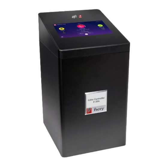
Figure 1: E-35A
14
Figure 2: Space Requirements for the E-35A Without Optional Furniture
16
Setting Customer Expectations
17
Unpacking the E-35A
18
Connecting the E-35A
19
About the Installation Process
15
Change the Language of the E-35A
15
Installing Hardware
15
Checking the Customer Site
16
Printer Readiness
16
Figure 3: Affixing the Decal to the Printer
19
Figure 4: E-35A Front and Connector Panel
20
(Optional) Connecting the Monitor, Keyboard, Mouse, and Power
21
Connecting to the Printer and the Network
21
Figure 5: Straight-Through and Crossover Ethernet Cables
22
Figure 6: Printer and E-35A Cable Connection
23
Figure 7: E-35A Power Switch
24
Figure 8: E-35A Power Button
24
Figure 9: USB Connection between Printer and E-35A
27
Figure 10: Fiery Ticker Status Bar
29
Using the E-35A
29
About Configure
30
Command Workstation
30
Fiery Quicktouch
31
Overview of Fiery Quicktouch Menu Options
32
Completing the Installation
28
Fiery Ticker
29
Printing E-35A Pages from the Monitor, Keyboard, and Mouse
29
Starting the E-35A for the First Time
24
Configuring a Static IP Address for the E-35A
25
Enabling the Power Synchronization
26
Figure 12: Fiery Quicktouch Home Screen
32
Figure 13: Queue Jobs Window
34
Figure 14: Printed Jobs Window
34
Figure 16: Quick Options Menu
36
Figure 17: the Printer Touch Panel
36
Figure 18: Ethernet Network Port (Upper RJ-45)
41
Network Status Leds
41
Starting, Shutting Down, Restarting, and Rebooting
41
Figure 19: E-35A Power Switch
42
Figure 20: E-35A Power Button
42
Overview
45
Replacing Parts
45
E-35A Diagrams
46
Using the Printer Touch Panel
36
Job List Tab
37
Main Tab
37
Printme Tab
37
Tools Tab
37
Fiery Tab
38
Printable Info Menu
39
Using the Fiery Desktop on the Printer Touch Panel
40
Figure 21: E-35A Front and Connector Panel
46
Figure 22: Exploded View of E-35A
47
Figure 24: Removing the Chassis Cover
50
Figure 25: Replacing the Chassis Cover
51
Fiery Quicktouch Display Module
52
Figure 26: Removing/Replacing the Front Panel
52
Figure 27: Removing Fiery Quicktouch Connectors
53
Figure 28: Removing/Replacing the Fiery Quicktouch
54
Removing and Replacing E-35A Internal Components
55
Figure 29: Printer Interface Board
56
Printer Interface Board
56
Figure 30: J102 Connector on the Printer Interface Board
57
Motherboard
57
Motherboard Replacement Overview
58
Figure 31: Diagram of the E-35A Motherboard
59
Removing the Motherboard
59
Replacing the Motherboard
61
Verifying New Motherboard Installation, and Transferring Options and BIOS Information
64
DIMM
67
Figure 32: Releasing a DIMM
67
CPU and CPU Cooling Assembly
68
Figure 33: CPU Cooling Assembly
68
Figure 34: Removing the CPU Cooling Assembly
69
Figure 35: Removing/Replacing the CPU
70
Motherboard Battery
72
Figure 36: Motherboard Battery
73
Chassis Fan
74
Motherboard Jumpers
74
Figure 37: Removing/Replacing the Chassis Fan
75
Power Supply
76
Figure 38: Removing the Power Supply
77
Hard Disk Drive (HDD)
78
Figure 39: Removing the HDD Assembly
80
Figure 40: Removing the HDD Bracket
81
Restoring and Verifying Functionality after Service
82
Performing Backup and Restore
84
Backup Recommendations
85
When Backing up an Existing E-35A Installation
85
Backing up the System Configuration
86
Restoring the System Configuration
87
Using Fiery System Restore
88
Platform Utilities
92
Using Bootable Backup Media to Restore
92
Installing System Software
94
When You Reinstall the System Software
94
Installing the System Software
96
Fiery Installer Builder
97
Download the System Software
98
Install the System Software Using the Prepared USB Flash Drive
99
Prepare the USB Flash Drive
99
Install the System Software Using the Prepared Replacement SATA HDD
100
Prepare the SATA HDD for Replacement
100
System Software Installation Error Messages
102
System Updates
102
Checking External Connections
103
Preliminary On-Site Checkout
103
Troubleshooting
103
Checking Internal Components
104
Inspecting the System
104
Error Messages and Conditions
108
Job Error Report
114
Troubleshooting Information
114
System Logs
115
Hardware Features
116
Networking and Connectivity
116
Physical Specifications
116
Safety and Emissions Compliance
116
Specifications
116
User Software
116
EMI/EMC Approvals
117
Safety Approvals
117
Figure 41: E-35A Installed on the Furniture
118
Procedures
118
Servicing the System with Furniture
118
Index
120
Figure 23: Cable Connections Inside the E-35A
48
Accessing Internal Components
49
Opening the E-35A
49
Shutting down the System
49
Figure 11: Fiery Quicktouch Panel
32
Figure 15: Quick Launch Menu
35
Quick Launch Menu
35
Quick Options
35
Advertisement
Advertisement
Related Products
EFI E-36A
EFI E-42B
EFI E-43A
EFI E-45
EFI E-85A
EFI EB-34
EFI E-85
EFI E-46A
EFI E-820
EFI E-45A
EFI Categories
Controller
Printer
Printer Accessories
Print Server
Server
More EFI Manuals
Login
Sign In
OR
Sign in with Facebook
Sign in with Google
Upload manual
Upload from disk
Upload from URL