Table of Contents
Advertisement
Quick Links
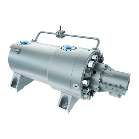
WIK Centrifugal Pumps
Radially Split, Multistage Barrel Pump, Cartridge
PCN=BO2662 5/09 (E)
Original Instructions
Type:
Size:
Serial No.:
Customer:
Customer Order No.:
Equipment/Item No.:
These instructions must be read prior to installing,
operating, using and maintaining this equipment.
WIK
USER INSTRUCTIONS
Installation
Operation
Maintenance
Advertisement
Table of Contents

Subscribe to Our Youtube Channel
Related Manuals for Flowserve WIK Series


Summary of Contents for Flowserve WIK Series
- Page 1 USER INSTRUCTIONS WIK Centrifugal Pumps Installation Operation Maintenance Radially Split, Multistage Barrel Pump, Cartridge PCN=BO2662 5/09 (E) Original Instructions Type: Size: Serial No.: Customer: Customer Order No.: Equipment/Item No.: These instructions must be read prior to installing, operating, using and maintaining this equipment.
-
Page 2: Table Of Contents
WIK USER INSTRUCTIONS ENGLISH BO2662 5/09 TABLE OF CONTENTS INTRODUCTION AND SAFETY ....4 INSTALLATION......... 15 General ..........4 Location ..........15 CE marking and approvals ....4 Part assemblies ........16 Disclaimer ..........4 4.2.1 Leveling Tools and equipment .... 16 Copyright .......... - Page 3 WIK USER INSTRUCTIONS ENGLISH BO2662 5/09 Stopping and shutdown ...... 36 6.9.1 Internal Assembly ........ 59 5.9.1 From on-line operation to cold 6.9.2 Casing Cover ........62 shutdown ..........36 6.9.3 Rotor Alignment ........63 5.9.2 From on-line operation to hot 6.9.4 Mechanical Seal ........
-
Page 4: Introduction And Safety
In spite of all the efforts information about the product in its installation and of Flowserve to provide sound and all necessary operation or about its support products, repair and information the content of this manual may diagnostic services. -
Page 5: Safety
This symbol indicates “hazardous substances mount expansion joints, unless authorized by and toxic fluid” safety instructions where non- Flowserve in writing, so that their force, due to internal pressure, acts on the pump flange. compliance would affect personal safety and could result in loss of life. -
Page 6: Products Used In Potentially Explosive Atmospheres
To lift heavy pieces above 25 kg (55 lb.) use an Where Flowserve has supplied only the bare shaft appropriate crane for the mass and in accordance pump, the Ex rating applies only to the pump. The with current local regulations. - Page 7 ATEX Ex rating on the nameplate. These are based clearances, bearing housings and motors. on a maximum ambient of 40°C (104°F); refer to Flowserve for higher ambient temperatures. 1.6.4.4 Preventing the build up of explosive mixtures The surface temperature on the pump is influenced by the temperature of the liquid handled.
-
Page 8: Safety Labels
WIK USER INSTRUCTIONS ENGLISH BO2662 5/09 appropriate dry run protection device is The responsibility for compliance with recommended (e.g. liquid detection or a power maintenance instructions is with the plant monitor). operator. To avoid potential hazards from fugitive emissions of To avoid potential explosion hazards during vapor or gas to atmosphere the surrounding area maintenance, the tools, cleaning and painting... -
Page 9: Transport And Storage
Boxes, crates, pallets or cartons may be unloaded Flowserve ships the pump mounted on its baseplate using forklift vehicles or slings dependent on their and soleplates, which is secured to a skid formed of size and construction. -
Page 10: Lifting
WIK USER INSTRUCTIONS ENGLISH BO2662 5/09 Lifting possible; otherwise remove the item. See Figure 2-1: Baseplate mounted Pump & Driver Lifting. EQUIPMENT CAPACITY 4) Insure that hoist is over center of gravity of Make sure that any equipment used to lift the pump baseplate and that cables are not cutting into or any other of its components is capable of any item. -
Page 11: Multistage Internal Assembly: Cartridge Barrel Pump
WIK USER INSTRUCTIONS ENGLISH BO2662 5/09 d) Verify that cables will not cut into pump cover [1460] and bottom of box for cable: (see panels, piping, etc. Remove any items that Cartridge Assembly Lifting Points Figure 2-3). will be damaged or protect items with wood blocks See Figure 2-2: Barrel Pump Lifting. -
Page 12: Multistage Shaft
Storage Figure 2- 4: Rotor Lifting Points This section provides storage data for pumps and parts manufactured by Flowserve. Storage data for 3) Adhere to the following task outline for uncrating drivers and other auxiliary equipment may be found and subsequent handling of the rotor: in section 10 of this manual. -
Page 13: Rotor Preservative Standards
WIK USER INSTRUCTIONS ENGLISH BO2662 5/09 2.4.1.1 Precautions at job site 2.4.1.5 Long-term outdoor storage 1) Do not allow the unit to rest in direct sunlight. The precautions for long-term outdoor storage are Sunlight will cause rapid condensation of the same as for long-term indoor storage, with the atmospheric moisture on the pump, resulting in following additional precautions taken at the site: corrosion of pump surfaces. -
Page 14: Depreserving
[1460]. This is necessary to equipment (see section 8 and section 10). prevent the diffuser from rotating. Moreover, a diffuser that is machined to the intermediate cover [1460] is considered by Flowserve to be inseparable. Page 14 of 76... -
Page 15: Suction Spacer Casing And Discharge Spacer Casing
3) Sufficient net positive suction head (NPSH) at drawings in section 10. suction flange of pump. 3.3.10 Baseplates The pump is factory mounted on a baseplate and its driver (if furnished by Flowserve) is mounted on a Page 15 of 76... -
Page 16: Part Assemblies
WIK USER INSTRUCTIONS ENGLISH BO2662 5/09 Part assemblies driver and pump make up the entire train; your baseplate would be less the innermost set of pads, which are labeled C-D in the baseplate top view In the context of this subsection the term figure. -
Page 17: Baseplates In Train
WIK USER INSTRUCTIONS ENGLISH BO2662 5/09 baseplate is not level, loosen anchor nuts, re- FOUNDATION BOLT (TYPICAL) Ievel it, retighten nuts, and recheck for nominal gradient. Continue this process until the PIPE SLEEVE baseplate is anchored and level. (TYPICAL) 4.2.3 Baseplates in train Where driver, pump, and any other unit that couples in train with the pump will be mounted on separate... -
Page 18: Grouting With Epoxy
WIK USER INSTRUCTIONS ENGLISH BO2662 5/09 1) According to your installation, verify: Soleplates below. To keep form from floating, a) That soleplates have been separated from anchor securely and shore around the cradle and pump, leveled, and aligned as applicable plate. described in section 4.5 b) That driving units (i.e., motor, fluid drive, gear, clutch, etc.) have been removed from... -
Page 19: Initial Alignment
Although in some cases Flowserve does ship the baseplate. driver mounted on the baseplate with the pump, the driver shaft is not precisely aligned with the pump 4) In accordance with the epoxy manufacturer's shaft;... -
Page 20: Installing Coupling
WIK USER INSTRUCTIONS ENGLISH BO2662 5/09 4) That pump hold down bolts are tight. centerlines for exact match, the baseplate should be 5) That suction and discharge piping is not almost level. connected to pump until after completion of initial cold alignment; 6) Using optical alignment equipment, align 6) That the pads on baseplate or soleplate(s) and centerline of every baseplate within 0.38 mm... -
Page 21: Figure 4- 5 : Alignment Orientation
WIK USER INSTRUCTIONS ENGLISH BO2662 5/09 DIAL INDICATORS All indicator readings must be taken on the periphery or rim of the coupling hub or shaft, and recorded as viewed from the fixed unit (see Figure 4-5 Alignment Orientation). Attach bracket to the movable unit coupling hub or shaft. -
Page 22: Piping
When installing piping, Flowserve recommends: VAPOR POCKET INCORRECT CORRECT VAPOR POCKET... -
Page 23: Installing Nozzle Extensions
4.6.1.3 Auxiliary piping Figure 4-8 Suction Piping Temporary Screen below made from No. 14 mesh stainless steel When Flowserve supplies auxiliary piping, it is wire backed with 16-gauge perforated plate, at normally fitted to the pump before shipment, or near the suction nozzle of the pump (the inlet complete with all necessary pressure gauges, flow nozzle of the HPRT). -
Page 24: Seal Piping Flushing And Cleaning
IEC60079-14 is an additional requirement for making electrical connections. Flowserve recommends either the use of a double-reverse dial indicator or laser alignment It is important to be aware of the procedure for alignment of pump and driver. If laser... -
Page 25: Setting Driver Shaft End Space
WIK USER INSTRUCTIONS ENGLISH BO2662 5/09 provided by the manufacturer of the laser alignment documentation in Section 10 or the Outline equipment. section 8. 4) Set end space by pushing shaft back in toward sleeve bearing 3 mm (0.13 in.) (See Figure 4-9 4.8.1 Setting driver shaft end space Motor Shaft Running Space above). -
Page 26: Cold Alignment
To bring the driver shaft in cold alignment with pump shaft, proceed as follows: Use of a shaft alignment graph, such as Flowserve Shaft Alignment Calculator (see Figure 4- 1) Verify that the requirements of the following 11 Shaft Alignment Calculator) aids and simplifies paragraphs in this subsection have been the alignment process. -
Page 27: Figure 4- 11 : Shaft Alignment Calculator
WIK USER INSTRUCTIONS ENGLISH BO2662 5/09 Fixed Unit Scale Movable Unit Scale 50 cm 100 cm 150 cm 200 cm 20 in. 40 in. 60 in. 80 in. Vertical Movement Calculations ÷ 2 = ÷ 2 = Set Bar Sag Set Bar Sag Indicator Indicator... -
Page 28: Hot Alignment
WIK USER INSTRUCTIONS ENGLISH BO2662 5/09 24) Install flat strap across hub of driver half 18) Check hold down bolt positions on the graph or coupling by bolting to flange in two places. otherwise determine the amount of shims to be added for the vertical correction, and the Unless hub is strapped down, it will vibrate movement required for the horizontal correction,... -
Page 29: Protection Systems
If in doubt consult Flowserve. 4) Check all auxiliary components such as indicators, filters, heat exchangers, control If there is any possibility of the system allowing the... - Page 30 WIK USER INSTRUCTIONS ENGLISH BO2662 5/09 new section fabricated, or lube oil reservoir is 7) Start auxiliary or spare lube oil pump and repaired. operate it until the system is filled with lube oil and all air is expelled from the system. 8) Close vent valves in the filter and heat 5.1.2.4 Servicing empty lube oil system exchanger.
-
Page 31: Pump Lubricants
WIK USER INSTRUCTIONS ENGLISH BO2662 5/09 2) Start auxiliary or spare lube oil pump. Verify that lube oil pressure indicator that is located 5) Start circulation in warm-up circuit and monitor downstream of backpressure control valve reads flow, temperature, and pressure (see your the same as in step 5 of section 5.1.2.4 above. -
Page 32: Lube Oil Change Recommendations
Lube oil change recommendations 5.2.4 Flushing and cleaning lube oil system Flowserve recommends that the lube oil in the pump During work on the piping of a pump, dirt, grit, and be inspected periodically, at least weekly, and chips are apt to accumulate inside the piping. This... -
Page 33: Impeller Clearance
WIK USER INSTRUCTIONS ENGLISH BO2662 5/09 pump; then clean and reinstall filter. Restart 3) Connect piping at all points. auxiliary lube oil pump and continue flush. 4) Operate pump (see section 5.7 and 5.8) for approximately 2 hours and during this time, periodically check differential pressure for an To prevent an accumulation of moisture indication of severe increase in differential... -
Page 34: Priming And Auxiliary Supplies
4) Check pressure gauge that is located in lube oil section 10.3 of this manual, Flowserve Engineering system instrument panel (see lube oil schematic drawings in back of this manual, or in your plant data drawing). -
Page 35: Operation
WIK USER INSTRUCTIONS ENGLISH BO2662 5/09 9) Check readings of the following instruments: 6) Check that lube oil outlet temperature indicator a) Pressure gauge in lube oil console should of driver bearings and speed increaser gear read pressure specified in lube oil schematic (when installed) are as required by the drawing in the back of this manual manufacturer (see driver and speed increaser... -
Page 36: Operating At Reduced Capacity
WIK USER INSTRUCTIONS ENGLISH BO2662 5/09 should both lube oil pumps lose pressure (see lube excess heat, the liquid will boil and the pump will oil console manufacturer's data in Section 10). become vapor bound and seize immediately. 11) Verify: Reducing capacity by throttling the a) That flow rate of pump is as required suction valve is ineffective and hazardous and... -
Page 37: From On-Line Operation To Hot Standby
WIK USER INSTRUCTIONS ENGLISH BO2662 5/09 heat exchangers, seal housings, and driver. To 1) See that valves in minimum flow circuit (see you determine cooling systems that are applicable to plant's data file) are open, then close discharge your pump see section 8 and piping drawings in valve (or place discharge valve in bypass). -
Page 38: 5.10.2 Balance
WIK USER INSTRUCTIONS ENGLISH BO2662 5/09 pressure head in the diffuser passages. Leaving the 5.10.3 Minimum flow diffuser, the liquid enters the intermediate cover Another phenomenon of the multi-stage pump is for [1460] where it is directed into the inlet of the next the temperature of the liquid to rise progressively as impeller. -
Page 39: 5.10.9 Thermal Expansion
Thus to preclude lubricating oil (lube oil) required, dates of inspection such imminent damage to a Flowserve multistage and service, and conditions observed during each pump when using an acid or caustic wash to clean a inspection. -
Page 40: Lube Oil System Component Maintenance
WIK USER INSTRUCTIONS ENGLISH BO2662 5/09 6.1.4 Lube oil system component maintenance 6.1.4.2 Repairing and adjusting lube oil system component 6.1.4.1 Replacement lube oil system component See manufacturer's instructions in section 10 and your plant's data file for information. Isolation valves permit replacement of lube oil system components without draining the piping. -
Page 41: Spare Parts
Rotor preservative standards 6.2.1 Ordering of spares 1) Rotors and complete internal assemblies are Flowserve keep records of all pumps that have been fully coated with a petroleum-based rust supplied. When ordering spares the following preventative. information should be quoted:... -
Page 42: Maintenance Tools And Equipment
3 /4 i n . (1 9 m m ) Di a . 3 6 to 4 8 i n . (0 .9 to 1 .2 m ) The Flowserve Sales Representative in your area will gladly review the class of spares best suited to your requirement. -
Page 43: Torque Procedure Pump Foot Hold- Down Bolts
WIK USER INSTRUCTIONS ENGLISH BO2662 5/09 followed, the flanges can be cocked, resulting in nuts will rotate. Look for severe galling, pitting, joint leakage and possible component damage. etc. If any of the above mentioned items are 5) Repeat step 4, increasing torque to damaged beyond repair, replace that item. -
Page 44: Setting Impeller Clearance
WIK USER INSTRUCTIONS ENGLISH BO2662 5/09 4 Bolt Pattern 8 Bolt Pattern 12 Bolt Pattern 16 Bolt Pattern 20 Bolt Pattern 24 Bolt Pattern TORQUE PATTERN CHART Figure 6- 2 : Torque Pattern Chart Setting impeller clearance 6.7.1 General instructions Please refer to sectional drawing in section 8 or 6.7.1.1 Items and details excluded from operating specification in section 10.3 for values:... -
Page 45: Figure 6- 3 : Task Schedule For Inspection, Repair
Figure 6- 3 : Task Schedule for Inspection, Repair, seal, Flowserve recommends the installation (or and Assembly of Internal Assembly assembly) of major parts according to the schedules... -
Page 46: Figure 6- 4 : Task Schedule For Installation Of Major Part/Assembly
WIK USER INSTRUCTIONS ENGLISH BO2662 5/09 PART/ASSEMBLY TASK SCHEDULE INSTALL INTERNAL INTERNAL ASSEMBLY ASSEMBLY INSTALL HEAD WITHOUT SEAL HOUSINGS CENTER ROTOR AND DOWEL HOUSINGS, IF NECESSARY INSPECT, CLEAN, AND REPAIR BEARING PARTS SET ROTOR REPLACEMENT RUNNING BEARING HOUSING POSITION ENSURE SEAL HOUSING IS REMOVED CENTER ROTOR... -
Page 47: Coupling Removal
WIK USER INSTRUCTIONS ENGLISH BO2662 5/09 6.7.2 Coupling removal The procedures outlined in this subsection do not apply to keyless hydraulic fit couplings. For installation or removal of such couplings, refer to the applicable drawings in the back of this manual, see section 10. Removal of the coupling halves should be performed by application of an even heat;... -
Page 48: Figure 6- 7 : Typical Alignment Tool
WIK USER INSTRUCTIONS ENGLISH BO2662 5/09 d) Assembly skid is bolted tightly against c) Continue to push the cartridge assembly baseplate making track completely into the alignment tool, using a hydraulic immobile. ram if necessary. 7) Lubricate top of track so that cartridge d) Install the studs provided with alignment assembly will slide easily. -
Page 49: Main Lube Oil Pump Removal
WIK USER INSTRUCTIONS ENGLISH BO2662 5/09 attach it to a nylon lifting strap located at sleeve, necessitating the removal of pieces rather the center of gravity of the assembly. than the intact seal unit. Carefully lift cartridge assembly off of blocks and remove it from the alignment 2) If cartridge type mechanical seals are tool. -
Page 50: Mechanical Seal
WIK USER INSTRUCTIONS ENGLISH BO2662 5/09 9) Disassemble double thrust bearing [3032] as 6.7.6 Mechanical seal follows: a) Remove thrust bearing shoes from top half 6.7.6.1 Removing seal unit of base rings. Then remove top half of Remove the seal unit in accordance with the seal base rings with leveling plates attached. - Page 51 WIK USER INSTRUCTIONS ENGLISH BO2662 5/09 2) When removing balance drum bushing [1600], protected with heat-resistant gasket note method used by factory for retaining material or equivalent to prevent damage bushing to casing cover [1221], if any; then to the shaft [2100] due to dropped use rotary file and grind off tack welds or stake components marks, whichever is applicable, and remove...
- Page 52 WIK USER INSTRUCTIONS ENGLISH BO2662 5/09 4) Install lifting gear on part, if necessary, then lift 3) Remove balance drum split ring retainer screw part clear of assembly and set it aside. [6570.5], split ring retainer ring [2530.2] and Remove lifting gear. split ring [2531.2], if applicable.
- Page 53 WIK USER INSTRUCTIONS ENGLISH BO2662 5/09 c) Heat and remove suction impeller [2200.1] not lift the shaft enough to apply force to the cover using the procedure outlined in section or spacer as this may bend the shaft. 6.7.8.1 above. Remove split ring [2531.1] (if installed) and impeller key(s) [6700.4].
-
Page 54: Part Cleaning, Inspection, And Repair
The thrust bearing shoes, base ring halves, and inspection, should you require additional sleeve bearing halves must be replaced in sets. information about a condition or repair which is not covered here, contact your nearest Flowserve 6.8.2.4 Mechanical seal Service Department (see section 6.2.1) 6.8.2.4.1 Disassembling Seal Unit 6.8.1... - Page 55 WIK USER INSTRUCTIONS ENGLISH BO2662 5/09 5) Using same method as was observed in step straight shaft are required (see section 2 above, tack weld bushing using welding wire 6.8.2.7.3 below). and gas-tungsten arc or install set screws in 2) All internal castings (intermediate covers, bushing and parent part.
- Page 56 [2100] while it is given in the section 10.3, contact your nearest rotated but particularly at bearing journal Flowserve Sales Office for recommendations [3020] areas and adjacent to the ends of concerning your particular circumstance (see coupling keyway [6700.1];...
- Page 57 Place bearing details about obtaining undersized parts from surfaces in soft-faced V-blocks (or equivalent) Flowserve Service Department, see section 6.2.1 5) A record should be kept of the decrease in Rotating parts must be at room skirt and hub diameters and the undersize of temperature when performing step 5.
- Page 58 WIK USER INSTRUCTIONS ENGLISH BO2662 5/09 3) See that requirements under visual inspection 6.8.2.7.8 Replacing Bushings (section 6.8.2.7.1) above which apply to wear These instructions apply to the replacement of rings [1500] are in compliance with for new bushings [1610] in intermediate covers [1460] or ring.
-
Page 59: Pump Assembly
WIK USER INSTRUCTIONS ENGLISH BO2662 5/09 table; total runout shall not exceed heat wearing ring as described in step 2 until maximum given in section 10.3. ring will slip into place on skirt. 8) Install new wear ring locking keys [6700.3] and 5) If the replacement wearing ring [2300] has not tack weld them to metal of parent part using been furnished with finish stock left on the... - Page 60 WIK USER INSTRUCTIONS ENGLISH BO2662 5/09 cooling it with shop air or by allowing it to personnel injury and part damage due to be cooled by ambient air (do not use any dropping. other means to cool shaft) Always ensure that hot parts are handled with c) The shaft [2100], wearing rings 1500], soft cables or hands protected by heat- bushings [1600 &...
- Page 61 WIK USER INSTRUCTIONS ENGLISH BO2662 5/09 outlined in interference fit part installation c) Install the impeller [2200] on the impeller (section 6.9.1.1) above. key(s) [6700.4] and against the split ring 4) Place the shaft on the base assembly as [2531.1] (or shaft shoulder, if no split ring follows: is installed), using the procedure outlined a) Install lifting gear, if necessary, on the...
-
Page 62: Casing Cover
Figure 6- 8 : Rotor Lateral Movement For guidance in tack welding replacement 6.9.2 Casing Cover parts, contact your nearest Flowserve Sales Office The casing cover [1221] fits closely with a clearance (see section 6.2.1). of 0.03 to 0.10 mm (0.001 to 0.004 in.) between the casing cover [1221] and bore of the casing [1100]. -
Page 63: Rotor Alignment
WIK USER INSTRUCTIONS ENGLISH BO2662 5/09 spacer casing [1140], causing recirculation within e) Install inner retaining plate (if applicable), the pump and in turn erosion, particularly at its high thrust collar spacer sleeve (2460), and thrust pressure end, and decreased efficiency. collar key [6700.6] (if installed). - Page 64 WIK USER INSTRUCTIONS ENGLISH BO2662 5/09 bottom, top, and each side. Readings thus a) Set up dial indicator to read on face of thrust obtained must correspond to those given in collar [3610]. Hold shaft against thrust section 10.3. If necessary, reposition bearing bearings and rotate shaft [2100].
-
Page 65: Mechanical Seal
WIK USER INSTRUCTIONS ENGLISH BO2662 5/09 c) Reduce length by machining, or make a new 4) Oil all part surfaces before installing. longer thrust collar disc spacer [2460], as 5) Raise shaft slightly and roll bottom halves of required. sleeve bearing [3020] into bearing housings d) Reinstall parts. -
Page 66: Main Lube Oil Pump Installation
[3266], contact your nearest Flowserve Sales shaft, whichever is applicable, with set screw. Office (See section 6.2.1). -
Page 67: Cartridge Assembly Install
WIK USER INSTRUCTIONS ENGLISH BO2662 5/09 shaft, whichever is applicable (see assembly b) Flange of assembly skid presses solidly drawing). against the baseplate. 3) Keep half-coupling on lube oil pump shaft c) Feet press against a solid surface across aligned with spider so that half-coupling on lube their entire area oil pump shaft will mesh with spider and flanges d) Assembly skid is bolted tightly against... -
Page 68: Final Assembly Tasks
WIK USER INSTRUCTIONS ENGLISH BO2662 5/09 instructions) must be accomplished before operation 6.9.9 Final Assembly Tasks of the pump. If you have not already done so: 1) Remove thrust bearing end cover [3266]. Apply Installation of the coupling halves should be an even film of sealant to parting surface of end performed by application of an even heat;... -
Page 69: Faults; Causes And Remedies
Should observation of the pump (see section 6). That is, by questions arise, contact your nearest Flowserve knowing the operational behavior of the pump, which Sales Office. - Page 70 Check shaft runouts are within acceptable values. CONSULT FLOWSERVE. Rotating part rubbing on stationary part Check and CONSULT FLOWSERVE, if internally. necessary. Bearings worn Replace bearings. ...
- Page 71 Pu mp doe s not d el iv er l iqu id PROBABLE CAUSES POSSIBLE REMEDIES Impeller damaged or eroded. Replace or CONSULT FLOWSERVE for improved material selection. Leakage under sleeve due to joint Replace joint and check for damage.
- Page 72 (damage during assembly, incorrect damage or state of cleanliness during assembly, wrong type of bearing etc). assembly and type of bearing used. Remedy or CONSULT FLOWSERVE, if necessary. Damaged bearings due to Check contamination source and replace ...
-
Page 73: Parts List And Drawings
10.2 Change notes marking. If required, copies of other certificates sent If any changes, agreed with Flowserve, are made to separately to the Purchaser should be obtained from the product after its supply, a record of the details Purchaser for retention with the User Instructions. -
Page 74: Operating Specification
WIK USER INSTRUCTIONS ENGLISH BO2662 5/09 10.3 Operating specification PUMP SERIAL NUMBER BXXXXX-01 Pump design clearances are listed below. Use these clearances for restoration when clearances have increased approximately 50% as evidenced by a decrease in performance or excessive vibration Metric English Baseplate Installation... - Page 75 WIK USER INSTRUCTIONS ENGLISH BO2662 5/09 Destaging Spacer, Impeller Spacer Sleeve Thrust Collar Suction Spacer, Intermediate Cover, Discharge Spacer Part Installation Heat, maximum °C °F Impeller Pressure Reducing Sleeve Destaging Spacer, Impeller Spacer Sleeve Thrust Collar Suction Spacer, Intermediate Cover, Discharge Spacer Warm-up temperatures °C °F...
- Page 76 200 Pandan Loop, #06-03/04 Pantech 21 Singapore 128388 Telephone 65 775 3003 Fax 65 779 4607 Visit our web site at: www.flowserve.com To find your local Flowserve representative, please use the Sales Support Locator System found at www.flowserve.com Page 76 of 76...
Need help?
Do you have a question about the WIK Series and is the answer not in the manual?
Questions and answers