Sign In
Upload
Manuals
Brands
Flowserve Manuals
Water Pump
WIK Series
Flowserve WIK Series Manuals
Manuals and User Guides for Flowserve WIK Series. We have
1
Flowserve WIK Series manual available for free PDF download: User Instructions
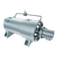
Flowserve WIK Series User Instructions (76 pages)
Radially Split, Multistage Barrel Pump, Cartridge
Brand:
Flowserve
| Category:
Water Pump
| Size: 1 MB
Table of Contents
Table of Contents
2
1 Introduction and Safety
4
General
4
CE Marking and Approvals
4
Disclaimer
4
Copyright
4
Duty Conditions
4
Safety
5
Summary of Safety Markings
5
Personnel Qualification and Training
5
Safety Action
5
Wik User Instructions English Bo2662
5
Products Used in Potentially Explosive Atmospheres
6
Safety Labels
8
Specific Machine Performance
8
Noise Level
8
2 Transport and Storage
9
Consignment Receipt and Unpacking
9
Receipt Inspection
9
Inboard and Outboard Bearing Shipping Shims
9
Handling
9
Wik User Instructions English Bo2662
9
Lifting
10
Baseplate-Mounted Pump and Driver
10
Soleplate-Mounted Barrel Pump
10
Figure 2- 1: Baseplate Mounted Pump & Driver Lifting
10
Multistage Internal Assembly: Cartridge Barrel Pump
11
Multistage Rotor
11
Figure 2- 2: Barrel Pump Lifing
11
Figure 2- 3: Cartridge Assembly Lifting Points
11
Multistage Shaft
12
Storage
12
Pump Preservative Standards
12
Figure 2- 4: Rotor Lifting Points
12
Rotor Preservative Standards
13
Depreserving
14
Recycling and End of Product Life
14
3 Pump Description
14
Configurations
14
Name Nomenclature
14
Design of Major Parts
14
Cartridge Assembly
14
Intermediate Cover Diffuser
14
Suction Spacer Casing and Discharge Spacer Casing
15
Wearing Rings and Bushings
15
Impellers
15
Bearings
15
Shaft Seals
15
Lube Oil System
15
Seal Piping
15
3.3.10 Baseplates
15
3.3.11 Drivers
15
3.3.12 Special Tools
15
Part Assemblies
16
Leveling Tools and Equipment
16
One Baseplate for Entire Train of Units
16
Figure 4- 1 : Baseplate Top View (Typical)
16
Baseplates in Train
17
Foundation
17
Level the Baseplate
17
Grouting
17
Grouting with Cement and Sand
17
Figure 4- 2 : Foundation Bolt
17
Grouting with Epoxy
18
Figure 4- 3 : Grouting Baseplates or Soleplates
18
Initial Alignment
19
Alignment Tools and Equipment
19
Alignment Accuracy
19
Reasons for Field Alignment of Pump and Driver
19
Alignment Preconditions
19
Installing Coupling
20
Alignment Procedure
20
Figure 4- 4 : Determining Bar Sag
20
Figure 4- 5 : Alignment Orientation
21
Figure 4- 6 : Dial Indicator Setup for Alignment
21
Piping
22
Recommendations and Notes for Piping Connects
22
Figure 4- 7 : Vapaor Pockets
22
Installing Nozzle Extensions
23
Figure 4-8 Suction Piping Temporary Screen
23
Seal Piping Flushing and Cleaning
24
4.6.3.1 Carbon Steel Piping
24
Electrical Connections
24
Final Shaft Alignment Check
24
Setting Driver Shaft End Space
25
Tapping Driver Mount Pads
25
Figure 4- 9 : Motor Shaft Running Space
25
Figure 4- 10 : Measuring Distance between Ends of Pump and Driver Shafts
25
Cold Alignment
26
Figure 4- 11 : Shaft Alignment Calculator
27
Figure 4- 12 : Alignment Measurement Points
27
Hot Alignment
28
Protection Systems
29
5 Commissioning Startup, Operation and Shutdown
29
Precommissioning Procedure
29
Readying and Servicing Driver
29
Readying and Servicing Pump and Auxiliary Systems
29
Pump Lubricants
31
Lubricating Oil
31
Lube Oil Change Recommendations
32
Oil Specifications
32
Flushing and Cleaning Lube Oil System
32
Impeller Clearance
33
Direction of Rotation
33
Guarding
33
Priming and Auxiliary Supplies
34
Starting the Pump
34
Operation
35
Checks and Minor Adjustments
35
Operating at Reduced Capacity
36
Stopping and Shutdown
36
From On-Line Operation to Cold Shutdown
36
From On-Line Operation to Hot Standby
37
Hydraulic, Mechanical and Electrical Duty
37
5.10.1 Pump Flow
37
5.10.2 Balance
38
5.10.3 Minimum Flow
38
5.10.4 Minimum Flow Orifice
38
5.10.5 Net Positive Suction Head
38
5.10.6 Shaft Seal
38
5.10.7 Cooling Water System
38
5.10.8 Lube Oil System
38
5.10.9 Thermal Expansion
39
6 Maintenance
39
Maintenance Schedule
39
Periodic Seal Replacement
39
Bearing Housing Gasket Material and Thickness
39
Acid or Caustic Wash
39
Lube Oil System Component Maintenance
40
Preventive Maintenance Schedule
40
Spare Parts
41
Ordering of Spares
41
Service Instructions
41
Storage of Spares
41
Rotor Preservative Standards
41
Recommended Spares and Consumable Items
41
Maintenance Tools and Equipment
42
Tools for Cartridge Assembly
42
Tools for Coupling
42
Tools for Bearings
42
Tools for Casing Cover (Head)
42
Tools for Internal Assembly
42
Fastener Torques
42
Single Row Cover-To-Case Bolting Metal-To-Metal Gasketed Joints
42
Figure 6- 1 : Roll and Heel Bars
42
Torque Procedure Pump Foot Hold- down Bolts
43
Setting Impeller Clearance
44
Disassembly
44
General Instructions
44
Figure 6- 2 : Torque Pattern Chart
44
Figure 6- 3 : Task Schedule for Inspection, Repair
45
Figure 6- 4 : Task Schedule for Installation of Major Part/Assembly
46
Coupling Removal
47
Removing Cartridge Assembly
47
Figure 6- 5 : Typical Tension Flange Arrangement
47
Figure 6- 6 : Typical Assembly Skid
47
Figure 6- 7 : Typical Alignment Tool
48
Main Lube Oil Pump Removal
49
Bearing Disassembly
49
Mechanical Seal
50
Casing Cover Removal and Disassembly
50
Part Cleaning, Inspection, and Repair
54
Cleaning
54
Inspection and Repair
54
Pump Assembly
59
Internal Assembly
59
Casing Cover
62
Figure 6- 8 : Rotor Lateral Movement
62
Rotor Alignment
63
Mechanical Seal
65
Bearing Assembly
65
Figure 6- 9 : Pressure Dam Bearing Alignment
65
Main Lube Oil Pump Installation
66
Cartridge Assembly Install
67
Coupling Installation
67
Final Assembly Tasks
68
7 Faults; Causes and Remedies
69
8 Parts List and Drawings
73
9 Certification
73
10 Other Relevant Documentation and Manuals
73
Supplementary User Instruction Manuals
73
Change Notes
73
Operating Specification
74
Advertisement
Advertisement
Related Products
Flowserve WDX R/C
Flowserve WDX E
Flowserve WDX S
Flowserve WK44
Flowserve Worcester V-Flow 53 Series
Flowserve Worcester V-Flow 54 Series
Flowserve Worcester WK70 Series
Flowserve Worcester WKB70 Series
Flowserve APEX W8000
Flowserve Worcester 14 Series
Flowserve Categories
Control Unit
Controller
Water Pump
Valve Positioners
Industrial Equipment
More Flowserve Manuals
Login
Sign In
OR
Sign in with Facebook
Sign in with Google
Upload manual
Upload from disk
Upload from URL