
Related Manuals for Stryker Secure II 3002


Summary of Contents for Stryker Secure II 3002
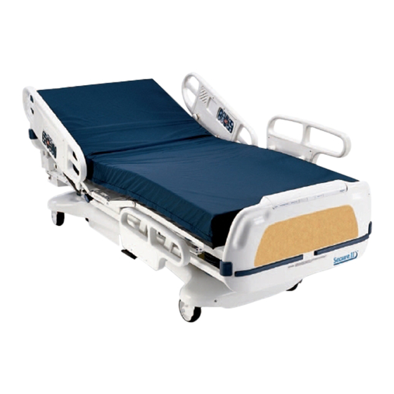
- Page 1 Maintenance Medical Manual Secure II Med-Surg Bed Model 3002 For parts or technical assistance call 800 327 0770 (option 2)
-
Page 2: Table Of Contents
Table of Contents Introduction Specifications ................Warning / Caution / Note Definition . - Page 3 Table of Contents Service Information Brake Pedal Replacement ............. . Lift Motor and Capacitor Removal and Replacement .
- Page 4 Table of Contents Assembly Drawings and Parts Lists Bed Assembly ..............98, 99 Base Assembly and Options .
- Page 5 Table of Contents Assembly Drawings and Parts Lists (Continued) Head End Siderail Latch Assembly ..........218 , 219 Foot End Siderail Assembly .
-
Page 6: Introduction
Introduction INTRODUCTION This manual is designed to assist you with the maintenance of the Stryker Model 3002 Secure II Bed. Read it thoroughly before using the equipment or beginning any maintenance on it. SPECIFICATIONS Safe Working Load 500 pounds (227 kilograms) -
Page 7: Warning / Caution / Note Definition
Introduction WARNING / CAUTION / NOTE DEFINITION The words WARNING, CAUTION and NOTE carry special meanings and should be carefully reviewed. WARNING Alerts the reader about a situation, which if not avoided, could result in death or serious injury. It may also describe potential serious adverse reactions and safety hazards. - Page 8 Use only a Stryker supplied interface cable. Use of any other cable may cause the bed to function improp- erly which may result in patient or user injury.
- Page 9 Introduction SAFETY TIPS AND GUIDELINES (CONTINUED) WARNING To avoid risk of electrical shock, unplug all power cords before opening the service compartment, junction box or receptacle. Do not use the optional 110V outlet for life sustaining equipment. To avoid pinching your fingers, place the IV pole in the upright position before using the drive handle . To avoid possible injury and to assure proper operation when using a powered mattress replacement system such as XPRT: Confirm proper scale system operation following mattress installation.
-
Page 10: Safety Tips And Guidelines
Introduction SAFETY TIPS AND GUIDELINES (ZOOM OPTION) In addition to the previous warnings and cautions, all of the following warnings and cautions apply to units equipped with the Zoomr option. WARNING The 3002 Patient Transport Frame is intended for use by trained hospital personnel only. Failure to prop- erly train personnel could result in injury. -
Page 11: Set−Up Procedures
WARNING Use only a Stryker supplied interface cable. Use of any other cable may cause the bed to function improperly which may result in patient or user injury. Ensure the siderails raise, lower and store smoothly and lock in the up position and in the intermediate... - Page 12 Claim will be limited in amount to the actual replacement cost. In the event that this information is not received by Stryker within the fifteen (15) day period following the delivery of the merchandise, or the damage was not noted on the delivery receipt at the time of receipt, the customer will be responsible for pay- ment of the original invoice in full.
-
Page 13: Bed Symbols
Symbols Warning, Refer to Service/Maintenance Manual Alternating Current Type B Equipment: equipment providing a particular degree of protection against elec- tric shock, particularly regarding allowable leakage current and reliability of the protec- tive earth connection. Class 1 Equipment: equipment in which protection against electric shock does not rely on BASIC INSULATION only, but which includes an additional safety precaution in that means are provided for the connection of the EQUIPMENT to the protective earth con- ductor in the fixed wiring of the installation in such a way that ACCESSIBLE METAL... -
Page 14: Bed Illustration
Bed Illustration HEAD END CPR Release Handle PATIENT’S LEFT PATIENT’S RIGHT Footboard Control Panel Siderail Release Handle Steer Pedal FOOT END Motion Interrupt Brake Pedal I.V. and Fracture Frame Mount Night Foley Bag Hook Light (Isolated) I.V. and (Optional Equip.) Fracture Frame Mount Foley Bag Hooks... -
Page 15: Brake Pedal Operation
Base Operation Guide BRAKE PEDAL OPERATION WARNING Always apply the caster brakes when a patient is getting on or off the bed. Push on the bed to ensure the brakes are securely locked. Always engage the brakes unless the bed is being moved. Injury could result if the bed moves while a patient is getting on or off the bed. -
Page 16: Cpr Emergency Release Usage
Litter Operation Guide CPR EMERGENCY RELEASE When quick access to the patient is needed, and the Fowler is raised, squeeze one of the two red release handles (see illustration, page 13) and the Fowler can be quickly guided down to a flat position. NOTE The handle can be released at any time to stop the Fowler from lowering. -
Page 17: Night Light Usage
Litter Operation Guide NIGHT LIGHT USAGE The bed is equipped with two night lights to illuminate the floor area around the bed. There is a switch under the litter thigh section on the pa- tient’s left side that turns both lights on and off. NOTE The night lights have a sensor so the lights will turn off, even when the switch is on, if the light in the room is bright... -
Page 18: Poles
Litter Operation Guide OPERATING IV POLES To use the 2−Stage Permanently Attached IV pole: NOTE The 2−stage permanently attached IV pole is an option and may have been installed at either the head, foot or both ends. The choice was made at the time the unit was purchased. -
Page 19: Positioning Siderails
Siderail Operation Guide POSITIONING SIDERAILS NOTE The siderails can be locked at two heights (intermediate & full up). The foot end siderails on a Short Bed do not have an intermediate position. The siderails can be tucked away under the bed when not in use. To remove the rail from the tucked position, grasp the top of the rail and pull outward. -
Page 20: Siderail Function Guide
Siderail Operation Guide INSIDE SIDERAIL FUNCTION GUIDE (Patient’s Right Rail) 1. Push to raise Knee Gatch. 2. Push to lower Knee Gatch. 3. Push to raise Fowler. 4. Push to lower Fowler. (Patient’s Left Rail) 1. Push to raise Fowler. 2. - Page 21 Siderail Operation Guide OUTSIDE SIDERAIL FUNCTION GUIDE (Patient’s Right Rail) 1. Push to raise Fowler. 2. Push to lower Fowler. 3. Push to raise Knee Gatch. 4. Push to lower Knee Gatch. " This panel is optional equipment. (Patient’s Left Rail) 1.
-
Page 22: Foot Board Control Panel Guide
Foot Board Operation Guide FOOT BOARD CONTROL PANEL GUIDE 1. Push repeatedly for low, medium and high settings for the siderail control panel lights. Pushing a fourth and fifth time will turn off the siderail lights and the red nurse call light respectively (see page 18). - Page 23 Foot Board Operation Guide FOOT BOARD CONTROL PANEL GUIDE (CONTINUED) 1. Push to raise Fowler. 2. Push to raise Knee Gatch. 3. Push to lower Fowler. 4. Push to lower Knee Gatch. " This panel is optional equipment. LED DISPLAY PANEL GUIDE The LED Display Panel is located at the foot end of the bed, under the Control Panel.
- Page 24 Foot Board Operation Guide CHAPERONEr BED EXIT (OPTIONAL EQUIPMENT) For beds with a scale system: NOTE If the weigh system is in use, it will switch to ”off” when the “ARM” key is pressed. 1. Before putting the patient on the bed, the weigh system must be zeroed for the Bed Exit System to func- tion properly (see page 26 for instructions on zeroing the weigh system).
- Page 25 Foot Board Operation Guide CHAPERONEr BED EXIT WITH ZONE CONTROL (OPTIONAL EQUIPMENT) For beds with a scale system: NOTE: If the weigh system is in use, it will switch to ”off” when Bed Exit is armed. 1. Before putting the patient on the bed, the weigh system must be zeroed for the Bed Exit System to func- tion properly (see page 26 for instructions on zeroing the weigh system).
-
Page 26: Scale System Operation Guide
Scale System Operation Guide SCALE SYSTEM CONTROL PANEL GUIDE (OPTIONAL EQUIPMENT) 1. LCD − displays patient weight. Trendelenburg angle is displayed when the scale is not active. 2. Press to zero bed (page 26). Also press to scroll while Menu Mode is active. 3. - Page 27 Scale System Operation Guide PREPARING THE BED FOR PATIENT STAY/ZEROING THE SCALE SYSTEM NOTE Do not zero the bed while a patient is in bed. If this should occur, remove the patient and zero the bed again. If Bed Exit is armed, it must be disarmed before the scales can be zeroed. Prepare the bed for the patient’s stay by adding/removing linens, pillows, etc.
- Page 28 Scale System Operation Guide ADDING OR REMOVING ITEMS DURING A PATIENT’S STAY If it is necessary to add or remove items (monitors, pumps, etc.) during the patient’s stay, press and re- lease to activate the scale system. After the scale monitor reads: “XXX.X LB”, press and hold The scale monitor will read: “HOLD TO START”...
- Page 29 Scale System Operation Guide CONVERTING THE PATIENT’S WEIGHT Press and release The scale monitor will read: ”WEIGHT NOW KGS” ”XXX.X KG” Repeat the procedure to return to pounds. The display will read: ”WEIGHT NOW LBS” ”XXX.X LB” If the unit of measurement has been locked, the display will read: “UNITS ARE LOCKED”...
- Page 30 Scale System Operation Guide DISPLAYING THE WEIGHT LOG To display a list of the previous 10 weight readings, press to activate the scale system. The scale monitor will read: “LET GO FOR SCALE” “XXX.X LB” Press to enter the Menu Mode. The scale monitor will read: “YB FOR OPTIONS”...
- Page 31 Scale System Operation Guide VIEWING PATIENT WEIGHT IN GAIN/LOSS MODE To view the patient’s weight and to begin totaling the amount of weight the patient has gained or lost, press to activate the scale system. The scale monitor will read: “LET GO FOR SCALE”...
- Page 32 Scale System Operation Guide CHANGING THE NUMERICAL VALUE OF DISPLAYED WEIGHT To decrease the numerical value of the displayed weight, press to activate the scale system. The scale monitor will read: “LET GO FOR SCALE” “XXX.X LB” Press to enter the Menu Mode. The scale monitor will read: “YB FOR OPTIONS”...
-
Page 33: Pendant Controller
Optional Pendant Operation... - Page 34 Zoom Option Operation Guide DRIVE WHEEL OPERATION 1. Unplug the power cord from the wall socket and secure the cord sufficiently to prevent entangle- ment while the unit is in motion. The drive wheel will not operate if the power cord is plugged into the wall socket.
- Page 35 Zoom Option Operation Guide DRIVE WHEEL OPERATION (CONTINUED) 5. Grasp the drive handle at the two raised grip areas. Squeeze either of the motion release switches (A) located under the handle to enable the movement of the drive wheel. Either or both switches will enable movement but both switches must be released to stop movement.
- Page 36 Zoom Option Operation Guide HEAD END CONTROL PANEL OPERATION KNEE BACK DOWN ENGAGE DRIVE WHEEL RELEASE BRAKES PLUG BED IN TO CHARGE 1. Press and hold to raise the litter. 2. Press and hold to lower the litter 3. Press to raise the Knee section. 4.
- Page 37 Zoom Option Operation Guide BATTERY CHARGING AND OPERATION NOTE The bed may be equipped with a battery back−up option without the Zoomr drive wheel. 1. The unit has two 12 volt batteries to provide power to the drive wheel and back−up power to the unit func- tions if the power cord is unplugged from the wall socket.
-
Page 38: Preventative Maintenance
SOME CLEANING PRODUCTS ARE CORROSIVE IN NATURE AND MAY CAUSE DAMAGE TO THE PRODUCT IF USED IMPROPERLY. If the products described above are used to clean Stryker patient care equipment, measures must be taken to insure the beds are wiped with clean water and thoroughly dried fol- lowing cleaning. -
Page 39: Preventative Maintenance Checklist
Preventative Maintenance CHECKLIST All fasteners secure (reference all assembly prints) Engage brake pedal and push on the bed to verify all casters lock securely ”Brake Not Set” LED (on foot board) blinks when brakes are not engaged Locking steer caster engages and disengages properly Siderails move, latch and stow properly CPR release working properly Foot prop intact and working properly... -
Page 40: Static Discharge Precautions
2 and 3 of the following procedure. Do not place unprotected circuit boards on the floor. All circuit boards to be returned to Stryker Medical should be shipped in the static shielding bags the new boards were shipped in. - Page 41 Troubleshooting Guide NOTE pages 45−54 for an outline of bed PCB’s and voltage test points. PROBLEM/FAILURE RECOMMENDED ACTION No power to bed A. Verify the power cord connections at the wall and the bed. B. Check circuit breakers, under the litter/gatch section on the patient left side.
- Page 42 Troubleshooting Guide PROBLEM/FAILURE RECOMMENDED ACTION No bed up motion. A. Enter diagnostics, (see page 80) and press bed up. a. If motion is not present, go to step B. b. If motion is present, re−burn lift potentiometer limits, see page 65 for procedure.
-
Page 43: Troubleshooting Guide
Troubleshooting Guide This section of the troubleshooting guide includes the ZoomR self−propelled drive and the battery backup functions. When using this guide, assume the bed is functioning properly when powered by the AC line cord with the exception of the battery charging components. PROBLEM/FAILURE POSSIBLE CAUSE RECOMMENDED ACTION... - Page 44 Inverter/Charger, Battery & Zoom Troubleshooting Start Bed is not working Put the Bed in Drive mode Release the Brake Squeeze the Handle Bar Put ON/OFF Switch in switches ON position Recalibrate the Potentiometer Is the Bed moving (Control bar Refer to Bed POT Burn−in) Is the Power LED ON ? Troubleshooting GUide...
-
Page 45: Troubleshooting
Inverter/Charger, Battery & Zoom Troubleshooting Battery and Charger Module Is the Input supply Voltage Check Wall Outlet (~120V AC) Good? Connect Bed to Wall Power (~120V AC) Reset the Are the Circuit Breakers OK ? Circuit Breaker Is Battery Volage Sufficient? Replace the Batteries (>... - Page 46 Bed Circuit Boards CPU BOARD − 3002−407−950...
-
Page 47: Bed Circuit Boards
Bed Circuit Boards CPU BOARD − 3002−407−950 CABLE VOLTAGE POSITIVE NEGATIVE DESCRIPTION LOCATION LEAD LEAD +12 VDC Pin 1 Pin 4 or 5 Relays & Siderails Light Volt- +5 VDC Pin 2 & 3 Pin 4 or 5 +5 VDC from Power Supply −12 VDC Pin 6 Pin 4 or 5... - Page 48 Bed Circuit Boards SOFTWARE CONFIGURATION 1. Locate switch bank 4, labeled SB4 on the CPU board (see above). 2. Move the switches to the appropriate positions for the specific bed (see page 48 & 49). 3. To verify the switch settings, check what the foot board LCD displays in the burn−in mode. For beds with a scale system, select software config.
- Page 49 Bed Circuit Boards SOFTWARE CONFIGURATION (CONTINUED) FUNCTIONAL TEST ICU−KCI MED−SURG−KCI ICU−STANDARD BED ICU−ZOOM / STANDARD BED ICU−ZOOM / SCALE / BEDEXIT ICU−ZOOM / SCALE / ZONE CONTROL BEDEXIT ICU−SCALE / BEDEXIT ICU−SCALE / ZONE CONTROL BEDEXIT MED−SURG−STANDARD BED MED−SURG−ZOOM / STANDARD BED MED−SURG−ZOOM / SCALE / BEDEXIT...
- Page 50 Bed Circuit Boards SOFTWARE CONFIGURATION (CONTINUED) MED−SURG−ZOOM / SCALE / ZONE CONTROL BEDEXIT MED−SURG−SCALE / BEDEXIT MED−SURG−SCALE / ZONE CONTROL BEDEXIT MED−SURG−SHORT / ZOOM / STANDARD BED MED−SURG−SHORT / ZOOM / SCALE / BEDEXIT MED−SURG−SHORT / ZOOM / SCALE / ZONE CONTROL BEDEXIT MATERNITY...
- Page 51 Bed Circuit Boards POWER SUPPLY − P/N 59−157 CONNECTOR VOLTAGE POSITIVE LEAD NEGATIVE LEAD LOCATION 110V Pin 1 Pin 2 Pin 1 Pin 4 or 5 Pin 2 Pin 4 or 5 Pin 3 Pin 4 or 5 Pin 4 Pin 4 or 5 Pin 5 Pin 4 or 5...
- Page 52 Bed Circuit Boards ZOOMR OPTION INVERTER/CHARGER BOARD − PART NUMBER 3002−1−30 CONNECTOR VOLTAGE POSITIVE NEGATIVE DESCRIPTION LOCATION LEAD LEAD HDR 4 26 VDC Pin 2 Red Pin 1 Black From Battery − unplugged HDR 1 22 VAC Pin 3 Red Pin 2 Secondarys from Transformer −...
- Page 53 Bed Circuit Boards ZOOMR OPTION DISPLAY/CPU − P/N 2040−31−910 CONNECTOR VOLTAGE POSITIVE NEGATIVE DESCRIPTION LOCATION LEAD LEAD HDR 1 (H) 0−5VDC Pin 1 Pin 2 Control Pot Wiper Voltage (with Switch On) HDR 6 (J) Battery voltage around 26VDC Pin 1 Pin 5 Battery Voltage Return from On/Off Switch...
- Page 54 Bed Circuit Boards ZOOMR OPTION AC CROSSOVER BOARD − P/N 2040−31−900 CONNECTOR VOLTAGE POSITIVE LEAD NEGATIVE DESCRIPTION LOCATION LEAD HDR 5 (A) 120VAC Pin 4 Pin 1 AC Input to Board from the Inverter with the Power Cord Unplugged HDR 1 (C) 120VAC Pin 3 Pin 1...
-
Page 55: Bed Circuit Boards
Bed Circuit Boards OPTIONAL DC MOTOR POWER BOARD − P/N 2040−1−900 CONNECTOR VOLTAGE POSITIVE NEGATIVE DESCRIPTION LOCATION LEAD LEAD HDR 1 (P) Battery voltage around 26VDC Pin 3 Red Pin 1 Black Battery Voltage out to the Display/CPU Board HDR 2 (Q) 5VDC Disengaged Pin 1 Red Pin 3 Black... -
Page 56: Bed Communications Tester
3002−45−700 Optional Bed Communications Tester Item Part No. Part Name Qty. 3002−45−805 BCT Unit 3001−303−825 37−Pin Cable 3002−45−806 Instructions 3000−303−871 9V Battery... -
Page 57: Headwall Output Configuration
Head Wall Output Configuration 37−PIN CONNECTOR STRYKER PENDANT PORT Pin 1 Option 2 Common Pin 2 Read Light Pin 3 Room Light Pin 4 Speaker High Pin 5 Pot Wiper Pin 6 Radio Common Pin 7 Nurse Call Interlock Pin 8 Audio Transfer −... -
Page 58: Inverter Protection Features
Zoomr Option Inverter Protection Features The inverter has several features to prevent internal damage: 1. Low Battery Voltage − If the battery voltage at the inverter drops below the low voltage cut−off, the inverter will shut off. 2. Over−Temperature − If the inverter gets too hot, it will shut off. The overheating may be caused by high ambient temperature, blocked air flow or an overload condition. -
Page 59: Quick Reference Replacement Parts List
3002−700−30 CAPACITOR, FOWLER 59−780 CAPACITOR, FOWLER, 230V 3221−300−453 CAPACITOR, GATCH 59−779 CAPACITOR, GATCH, 230V 59−153 CAPACITOR, LIFT 59−778 CAPACITOR, LIFT, 230V 3221−200−243 CASTER, 6” 3001−200−60 CASTER, STEER, 6” 3001−200−50 CASTER, 8”, OPTIONAL 3001−200−90 *Call Stryker Technical Support (1−800−327−0770) for assistance. - Page 60 Quick Reference Replacement Parts List OTHER COMPONENTS (CONTINUED) CASTER, STEER, 8”, OPTIONAL 3001−200−80 COIL CORD, LIFT POWER 3001−200−824 COIL CORD, LIFT SENSOR 3001−200−815 COIL CORD, LITTER POWER 3001−300−844 COIL CORD, LITTER SIGNAL 3001−300−846 FOWLER BRAKE KIT 3001−300−775 LOAD CELL 3002−307−57 MOTOR COUPLER KIT, LIFT 3000−200−725 MOTOR, FOWLER W/CLUTCH...
-
Page 61: Service Information
Service Information BRAKE PEDAL REPLACEMENT Required Tools: 5/16” Hex Allen Wrench Torque Wrench Loctite 242 Hammer Punch #2 Phillips Screwdriver Procedure: 1. Unplug the bed power cord from the wall socket. 2. Using a #2 Phillips screwdriver, remove the three screws holding both the head end and the foot end up- per lift covers. -
Page 62: Lift Motor And Capacitor Removal And Replacement
Service Information LIFT MOTOR AND CAPACITOR REMOVAL AND REPLACEMENT Required Tools: 3/8” Socket Wrench w/Extension 5/16” Socket Wrench Floor Jack Side Cutters 7/16” Open End Wrench 2x4 (or Equivalent) FOOT END Procedure: NOTE If you need more space to work under the base frame, place a 2x4 across the base frame rails and use a floor jack to raise the base frame off the floor. -
Page 63: Lift Housing Removal And Replacement
Service Information LIFT HOUSING REMOVAL AND REPLACEMENT Required Tools: #2 Phillips Screwdriver Bungee Cord (or equivalent) 5/16” Socket Wrench Side Cutters 9/16” Socket Wrench 5/16” Nut Driver 7/32” Hex Allen Socket Wrench Sawhorses (or equivalent) T27 Torx 3/8” Socket Wrench (w/ approx. 6” extension) Procedure: 1. - Page 64 Service Information LIFT HOUSING REMOVAL AND REPLACEMENT (CONTINUED) FOOT END − BOTTOM VIEW 9. Lift the litter top up and support it about 6” above the lift screws with sawhorses or the equivalent. 10. Under the base, using a 9/16” socket, remove the four nuts (B) holding the lift housing to the base. 11.
-
Page 65: Lift Potentiometer Replacement And Adjustment
Service Information LIFT POTENTIOMETER REPLACEMENT AND ADJUSTMENT Required Tools: #2 Phillips Screwdriver Bungee Cord (or equivalent) 5/16” Socket Wrench 3/8” Open End Wrench Side Cutters Procedure: 1. Unplug the bed power cord from the wall socket. 2. Using a 5/16” socket wrench, remove the five bolts holding the lower lift cover to the base and remove the cover. -
Page 66: Lift Potentiometer "Burn−In" Procedure
Service Information LIFT POTENTIOMETER REPLACEMENT AND ADJUSTMENT (CONTINUED) 8. Lift up and out on the pot housing assembly to remove it from the lift housing. 9. Before installing the new pot on the bed, turn it clockwise until it stops. Turn it back counterclockwise two full (360_) revolutions. -
Page 67: Lift Motor Isolation Plate Replacement
Service Information LIFT MOTOR ISOLATION PLATE REPLACEMENT Required Tools: 7/16” Open End Wrench 5/16” Nut Driver or 5/16” Socket Wrench 3/8” Socket Wrench (w/6” ext.) Procedure: 1. Unplug the bed power cord from the wall socket. 2. Using a 5/16” socket wrench, remove the five bolts securing the lower lift cover and remove the cover. 3. -
Page 68: Lift Motor Coupler Replacement
Service Information LIFT MOTOR COUPLER REPLACEMENT Required Tools: 5/16” Socket Wrench 3/8” Socket Wrench (w/6” Extension) Floor Jack 2x4 (or Equivalent) Procedure: NOTE If you need more space to work under the base frame, place a 2x4 across the base frame rails and use a floor jack to raise the base frame off the floor. -
Page 69: Power And Sensor Coil Cord Replacement
Service Information POWER AND SENSOR COIL CORD REPLACEMENT Required Tools: #2 Phillips Screwdriver Side Cutters 5/16” Socket Wrench Bungee Cord (or equivalent) 5/16” Nut Driver Floor Jack 2x4 (or Equivalent) Procedure: NOTE If you need more space to work under the base frame, place a 2x4 across the base frame rails and use a floor jack to raise the base frame off the floor. - Page 70 Service Information POWER AND SENSOR COIL CORD REPLACEMENT ILLUSTRATION VIEW FROM CENTER OF BED...
-
Page 71: Zoomr Option Battery Removal And Replacement
Service Information ZOOMR OPTION BATTERY REMOVAL AND REPLACEMENT Required Tools: Torx T27 7/16” Wrench 1/2” Socket Wrench Bungee Cords Phillips Screwdriver 5/32” Allen Procedure: 1. Raise the litter to full up. Unplug the power cord from the wall socket and push the battery power on/off switch to the “OFF”... -
Page 72: Zoomr Option Power Board Removal And Replacement
Service Information ZOOMR OPTION DC MOTOR BOARD REMOVAL AND REPLACEMENT Required Tools: Phillips Screwdriver 1/8” Allen Wrench Bungee Cords T27 Torx Procedure: 1. Raise the litter to the full up position. 2. Unplug the power cord from the wall socket and push the battery power on/off switch to the “OFF” posi- tion. -
Page 73: Drive Motor Removal And Replacement
Service Information DRIVE MOTOR REMOVAL AND REPLACEMENT Required Tools: Phillips Screwdriver 1/2” Socket Wrench Bungee Cords Floor Jack T27 Torx Procedure: 1. Raise the litter to the full up position. 2. Unplug the power cord from the wall socket and push the battery power on/off switch to the “OFF” posi- tion. -
Page 74: Knee Motor Removal And Replacement
Service Information KNEE MOTOR REMOVAL AND REPLACEMENT Required Tools: T27 Torx Needle Nose Pliers 3/8” Socket Wrench Wire Cutters Procedure: 1. Electrically run the litter fully up. Unplug the bed power cord from the wall receptacle. 2. Using a 3/8” socket wrench, remove the two bolts holding the motion interrupt pan to the litter frame and remove the pan. -
Page 75: Head Motor Cam And Cam Guide Replacement
Service Information HEAD MOTOR CAM AND CAM GUIDE REPLACEMENT Required Tools: 5/16” Nut Driver 3/8” Socket Wrench T27 Torx Procedure: 1. Run the Knee Gatch fully up. Unplug the bed power cord from the wall socket. 2. Using a T27 Torx, remove the screw holding the foot end litter cover to the frame and remove the cover. 3. -
Page 76: Head Motor Limit Setting
Service Information LIMIT SETTING − HEAD MOTOR Required Tools: 5/16” Nut Driver T27 Torx Procedure: 1. Run the Knee Gatch fully up. 2. Using a T27 Torx, remove the screw holding the midsection litter access covers to the litter and remove the covers. -
Page 77: Head Motor Removal And Replacement
Service Information HEAD MOTOR REMOVAL AND REPLACEMENT Required Tools: 3/8” Socket Wrench Procedure: WARNING The head motor is not grounded and may be an electrical hazard. Use caution when working around motors. 1. Using the CPR release, lower the Fowler to flat (0_). 2. -
Page 78: Head Motor Drive Isolator And Cpr Decoupler Removal And Replacement
Service Information HEAD MOTOR DRIVE ISOLATOR AND CPR DECOUPLER REMOVAL AND REPLACEMENT Required Tools: 3/8” Socket Wrench Needle Nose Pliers Procedure: 1. Refer to page 76 for the ”Head Motor Removal and Replacement” procedure to access the isolator, springs and decoupler. 2. -
Page 79: Head Motor Drive Screw And Ball Nut Replacement
Service Information HEAD MOTOR DRIVE SCREW AND BALL NUT REPLACEMENT Required Tools: Large Snap−Ring Pliers 3/8” Socket Wrench (standard length bed actuator assembly shown) Procedure: 1. Run the bed fully up. Unplug the bed power cord from the wall socket. 2. -
Page 80: Head Motor Brake/Clutch Replacement
Service Information HEAD MOTOR DRIVE SCREW AND BALL NUT REPLACEMENT (CONTINUED) 10. To prevent the ball nut from coming off the drive screw, cable tie both ends of the ball nut to the drive screw. 11. Pull the drive screw toward the foot of the bed and remove the head end of the drive screw and ball nut assembly from the support. - Page 81 Service Information SCALE SYSTEM DIAGNOSTICS AND CALIBRATION Diagnostic Mode Functions: 1. ANGLE CALIBRATE − This may be required in the field to recalibrate the scale. Calibrate using 50 pounds. 2. DISP. CORNER LBS − This function displays the individual corner weights in pounds for each load cell assembly and can be used to isolate a defective load cell.
- Page 82 Service Information SCALE SYSTEM DIAGNOSTICS AND CALIBRATION (CONTINUED) Displaying Individual Load Cell Outputs (Continued): The two buttons listed below function as POSITION buttons to select the four corners of the bed’s litter. Whenever the LCD displays “ SELECT CORNER”, press one of these buttons to cycle through the corners and to select the load cell assembly at the desired corner.
-
Page 83: Scale System Diagnostics
Service Information SCALE SYSTEM DIAGNOSTICS AND CALIBRATION (CONTINUED) Scale Calibration (Continued): 6. If exactly 50 pounds is not available, change the display to match the weight you are using. Pressing the CHANGE EQUIP button will move the cursor position to the right. Pressing the up arrow (ZERO) button will increase the numbers. -
Page 84: Load Cell Replacement
Service Information LOAD CELL REPLACEMENT Required Tools: 1/4” Hex Allen Wrench Wire Cutters HEAD END Procedure: 1. Unplug the bed power cord from the wall socket. 2. Support the corner of the litter where the load cell is being removed. 3. -
Page 85: Power Supply Replacement
Service Information LOAD CELL REPLACEMENT (CONTINUED) NOTE If your bed is equipped with a scale system, there are two tapered shims (C) for each load cell. Refer to page as reference for proper installation of the shims. Proper installation of these shims is very important for scale accuracy. -
Page 86: Cpu Board Replacement
Service Information CPU BOARD REPLACEMENT Required Tools: T27 Torx Procedure: 1. Adjust the Fowler to approximately 25−30_. Unplug the bed power cord from the wall socket. 2. Properly ground yourself (see page 39 for static discharge precautions). 3. Using a T27 Torx, remove the two screws holding the head end litter access cover and remove the cover. 4. -
Page 87: Smart Tv Interface "Burn−In" Procedure
Service Information OPTIONAL SMART TV INTERFACE “BURN−IN” PROCEDURE This procedure is used for selecting the style of TV interface needed for your bed. If traditional TV is desired, no calibration is required. If optional Smart TV is available on the bed, select one of the TV manufacturers listed in the table below. -
Page 88: Zoomr Option Control Bar Potentiometer Replacement
Service Information ZOOMR OPTION CONTROL BAR POTENTIOMETER REPLACEMENT Required Tools: T27 Torx 1/2” Box End Wrench #2 Phillips Screwdriver Wire Cutters Small Flat Blade Screwdriver 5/16” Nut Driver Replacement Procedure: 1. Raise the litter and the head end to the full up position. 2. -
Page 89: Zoomr Option Control Bar Potentiometer "Burn−In" Procedure
Service Information ZOOMR OPTION CONTROL BAR POTENTIOMETER “BURN−IN” PROCEDURE Required Tools: T27 Torx 1/2” Box End Wrench #2 Phillips Screwdriver Wire Cutters Small Flat Blade Screwdriver 5/16” Nut Driver 1. If it has not already been done, follow steps 1 − 7 of the control bar potentiometer replacement procedure page 2. -
Page 90: Zoomr Option Ac Crossover Board Replacement
Service Information ZOOMR OPTION AC CROSSOVER BOARD REPLACEMENT Required Tools: T27 Torx 1/2” Box End Wrench #2 Phillips Screwdriver Wire Cutters Small Flat Blade Screwdriver Needle Nose Pliers 5/16” Nut Driver Replacement Procedure: 1. Follow steps 1 − 7 of the control bar potentiometer replacement procedure on page 2. -
Page 91: Siderail Cover Removal
Maintenance Procedures − Siderail HEAD AND FOOT SIDERAIL COVER REMOVAL Required Tools: #2 Phillips Screwdriver Removal Procedure: 1. Unplug the power cord from the wall receptacle. 2. Using a #2 Phillips screwdriver, remove the 8 phillips screws (A) holding the covers (B) to the siderail. CAUTION There are two cables connecting the outside cover to the head end siderail. -
Page 92: Molded Siderail Replacement
Maintenance Procedures − Siderail HEAD AND FOOT MOLDED SIDERAIL REPLACEMENT Required Tools: #2 Phillips Screwdriver 3/8” Nut Driver Procedure: 1. Unplug the bed power cord from the wall socket. 2. Remove the siderail cover (see page 90). 3. Using a 3/8” nut driver, remove the four screws (A) holding the molded rail (C) to the siderail support assembly (B). -
Page 93: Head End Siderail Cable Replacement
Maintenance Procedures − Siderail HEAD END SIDERAIL CABLE REPLACEMENT Required Tools: #2 Phillips Screwdriver Side Cutters Procedure: 1. Run the head section fully up. 2. Unplug the bed power cord from the wall socket. 3. Using a #2 Phillips screwdriver, remove the eight screws holding the siderail cover and remove the cover. 4. - Page 94 Maintenance Procedures − Siderail HEAD END SIDERAIL CABLE REPLACEMENT (CONTINUED) 6. Using side cutters, clip the cable ties (A) holding the cables together. 7. Using a #2 Phillips screwdriver, remove the cable clamp (C) from the siderail. 8. Disconnect cable (B) from the circuit board and cable (D) from the speaker. NOTE The speaker and nurse call are optional equipment and may not be in the siderail as shown.
-
Page 95: Siderail Assembly Removal
Maintenance Procedures − Siderail SIDERAIL ASSEMBLY REMOVAL Required Tools: T27 Torx Removal Procedure: 1. Run the head section up electrically when removing a head end siderail. 2. Unplug the bed power cord from the wall socket. 3. Lower the siderail being removed. NOTE If removing a head end siderail, the cable must be unplugged. -
Page 96: Foot Board Hinge Removal
Maintenance Procedures − Foot Board FOOT BOARD HINGE REMOVAL Required Tools: #2 Phillips Screwdriver Procedure: 1. Using a #2 Phillips screwdriver, remove the screws (A & B) holding the door and hinge assembly to the foot board. 2. If replacing the hinge only, use a Phillips screwdriver to remove the screws holding the hinge to the door. 3. -
Page 97: Foot Board Interface Plug Replacement
Maintenance Procedures − Foot Board FOOT BOARD INTERFACE PLUG REPLACEMENT Required Tools: #2 Phillips Screwdriver BOTTOM VIEW OF FOOT BOARD Procedure: 1. Unplug the bed power cord from the wall socket. 2. Remove the foot board from the bed to access the bottom of the board. 3. - Page 98 Notes...
-
Page 99: Assembly Drawings And Parts Lists Bed Assembly
Secure II Bed Assembly STANDARD BED SHOWN DETAIL A HEAD END SIDERAIL CABLE ROUTING Standard Bed Components Item Part No. Part Name Qty. Item Part No. Part Name Qty. (page 141−147) Litter Assembly 3−221 Hex Washer Hd. Screw (page 197−215) Lt. Hd. End Siderail Ass’y 3000−300−113 8”... - Page 100 Secure II Bed Assembly FOOT END SIDERAIL HEAD END SIDERAIL GROUND CONFIGURATION GROUND CONFIGURATION 8” Shorter Bed Components Standard Length Bed Components Item Part No. Part Name Qty. Item Part No. Part Name Qty. (page 141−147) Litter Assembly (page 141−147) Litter Assembly (page 197−215) Lt.
- Page 101 Base Assembly and Options HEAD END FOOT END...
-
Page 102: Base Assembly And Options
Base Assembly and Options Installation of Roll Pin into Brake Shaft Crank Typical 4 Places... - Page 103 Base Assembly and Options HEAD END...
- Page 104 Base Assembly and Options HEAD END LEFT SIDE FOOT END...
- Page 105 Base Assembly and Options Zoom Option Zoom Option Steer Option...
- Page 106 Base Assembly and Options Typical Both Ends Typical Both Ends...
- Page 107 Hex Washer Hd. Screw 23−80 Truss Hd. Screw (page 121.1) Uni−Pan Cover Assembly 3000−200−601 Brake Pedal Label 3000−200−602 Stryker Logo Label 3001−200−8 Bellows Bracket (page 131) Bottom Cover 3002−200−102 Base Weldment Base Assembly, Zoom Secure Bed − Part Number 3002−244−3 (Reference Only) Item Part No.
-
Page 108: Base Assembly And Options
Base Assembly and Options Base Assembly, Steer Option − Part Number 3001−999−137 (Reference Only) Item Part No. Part Name Qty. 3−349 Hex Hd. Cap Screw 5−20 Carriage Bolt 16−36 Nylock Nut 23−92 Truss Phillips Hd. Screw 30−52 Snap Bushing 38−414 Pedal Extension Spring 38−416 Lever Extension Spring... - Page 109 Lift Assembly (Head & Foot End) Top View 3001−200−251 (Foot − Standard Height) 3001−200−201 (Head − Standard Height) Item Part No. Part Name Qty. Item Part No. Part Name Qty. (page 109−111) Common Lift Assembly 3−128 Hex Washer Hd. Screw 3000−200−52 Bellows Bracket 3−121...
- Page 110 Lift Assembly (Common)
- Page 111 Lift Assembly (Common) Upper Lift Housing Ass’y Lower Lift Housing Ass’y Lift Motor Ass’y Idler Gear Ass’y Motor Pinion Gear Ass’y Idler Gear Ass’y (Manual Override Shaft) Inner Screw Ass’y Coupler Receiver Ass’y...
-
Page 112: Lift Assembly
Lift Assembly (Common) Item Part No. Part Name Qty. 3000−200−201 Upper Lift Housing 3000−200−202 Lower Lift Housing 3000−200−251 Outer Screw 3000−200−204 Upper Housing Sleeve 3000−200−205 Upper Stage Nut 3000−200−249 Inner Screw 3000−200−207 Lower Stage Nut 3000−200−208 Glide Bushing 3000−200−209 Motor Pinion Gear 3000−200−210 Idler Gear 3000−200−252... -
Page 113: Motor Isolation Plate Assembly
3000−200−723 Motor Isolation Plate Assembly Assembly part number 3001−200−214 (reference only) Item Part No. Part Name Qty. 3001−200−213 Isolation Plate 3000−300−442 Grommet... -
Page 114: Brake Shaft Assembly
Brake Shaft Assembly, Left and Right Assembly part number 3001−200−340 (Left) Assembly part number 3001−200−345 (Right) Item Part No. Part Name Qty. 3000−200−314 Brake Shaft 3001−200−325 Brake Pedal 4−270 Soc. Hd. Cap Screw... -
Page 115: Brake Crank Assembly
3002−201−330 Brake Crank Assembly Item Part No. Part Name Qty. 3002−201−309 Brake Cam Shaft Crank 14−4 Washer 3002−200−331 Brake Link 3002−200−332 Dog Leg Brake Link 2−108 Socket Hd. Shoulder Screw... -
Page 116: Brake Bar Assembly
3002−200−335 Brake Bar Assembly Item Part No. Part Name Qty. 5−18 Carriage Bolt 16−35 Nylock Hex Nut 3000−200−318 Guide Pin 3000−200−321 Brake Ring 3000−200−323 Brake Bar 3000−200−324 Brake Bar Bumper 3002−200−310 Brake Bar Return Spring... -
Page 117: Caster Assembly
3001−200−60 6” Caster Assembly Item Part No. Part Name Qty. (page 118) Wheel Assembly 16−60 Lock Nut 3−342 Hex Hd. Cap Screw 3001−200−61 Caster Horn w/Bearing... - Page 118 3001−200−50 6” Steer Caster Assembly Item Part No. Part Name Qty. (page 118) Wheel Assembly 16−60 Lock Nut 3−342 Hex Hd. Cap Screw 3001−200−51 Steer Caster Horn w/Bearing...
- Page 119 5000−2−10 6” Molded Wheel Assembly Item Part No. Part Name Qty. 81−226 Bearing 715−1−255 Wheel Bushing 5000−2−20 Molded Wheel 6060−2−46 Bearing Spacer...
- Page 120 3001−200−90 Optional 8” Caster Assembly Item Part No. Part Name Qty. (page 121) Wheel Assembly 16−60 Hex Nut 3−99 Hex Hd. Cap Screw 3001−200−76 Caster Horn...
- Page 121 3001−200−80 Optional 8” Steer Caster Assembly Item Part No. Part Name Qty. (page 121) Wheel Assembly 16−60 Hex Nut 3−99 Hex Hd. Cap Screw 3001−200−81 Caster Horn...
- Page 122 715−2−25 Optional 8” Wheel Assembly Item Part No. Part Name Qty. 52−503 Bearing Spacer 81−226 Bearing 715−1−255 Wheel Bearing 715−1−255 Wheel...
- Page 123 3002−300−10 Base Uni−Pan Cover Assembly Item Part No. Part Name Qty. 988−2−708 Service Caution Label 3002−300−9 Uni−Pan Cover 121.1...
- Page 124 Notes 121.2...
- Page 125 Base Assembly with Zoom Option HEAD END...
- Page 126 Base Assembly with Zoom Option HEAD END HEAD END See Detail A 3001−200−306 3001−200−306 DETAIL A...
- Page 127 Base Assembly with Zoom Option HEAD END HEAD END...
- Page 128 Base Assembly with Zoom Option FOOT END 8” Caster Option 6” Caster Option...
- Page 129 Base Assembly with Zoom Option FOOT END HEAD END...
- Page 130 Base Assembly with Zoom Option...
-
Page 131: Zoomr Option Drive Wheel Lift Lever Assembly
Base Assembly with Zoom Option... -
Page 132: Zoomr Option Bottom Covers
21−22 Set Screw 2040−1−804 Pwr. Bd. DC Pwr. Cable 23−25 Hex Washer Hd. Screw 3000−200−601 Brake Label 23−281 Self−Tapping Screw 3000−200−602 Stryker Logo Label 25−79 Pop Rivet 3000−300−58 Limit Switch 26−261 Groove Pin 3000−300−428 Gatch Link Sleeve 26−277 Clevis Pin 3000−300−113... -
Page 133: Zoomr Option Drive Train Assembly
Zoom Option Drive Wheel Lift Lever Assembly Assembly part number 2040−1−12 (reference only) Item Part No. Part Name Qty. 11−3 Washer 26−297 Clevis Pin 27−21 Rue Ring 45−232 O−Ring 81−70 Flange Bearing 2040−201−13 Drive Wheel Lift Plate Ass’y 2040−1−87 Lift Lever Roller 2040−1−99 Lift Lever Guide... -
Page 134: Zoomr Option Battery Tray Assembly
3001−200−22 Foot End Bottom Cover Item Part No. Part Name Qty. 3002−1−100 Bottom Cover 3000−000−039 Grommet 2040−1−17 Zoom Option Head End Bottom Cover... -
Page 135: Zoomr Option Base Power Assembly
3002−1−14 Zoom Option Drive Train Assembly Item Part No. Part Name Qty. 8839−793−700 Hex Hd. Cap Screw 4−338 Flanged But. Hd. Cap Screw 11−262 Washer 3−54 Hex Hd. Cap Screw 3002−1−72 Drive Train Motor 2040−1−73 Gear Box 2040−1−74 Drive Train Wheel 2040−1−75 Motor Mounting Bracket 2040−1−97... - Page 136 Zoom Option Battery Tray Assembly Assembly part number 3002−1−15 (reference only) WIRING VIEW Item Part No. Part Name Qty. 4−46 But. Hd. Cap Screw 16−28 Nylock Nut 23−256 Pan Hd. Screw 38−151 Cable Tie 2040−1−70 Battery 2040−1−802 Battery Jumper Cable 3000−300−2 Push Nut 3002−1−69...
- Page 137 3002−1−30 Zoom Option Base Power Assembly Item Part No. Part Name Qty. 4−263 But. Hd. Cap Screw 4−315 But. Hd. Cap Screw 12−6 Helical Lock Washer 14−4 Nylon Washer 16−2 Fiberlock Nut 59−187 Spacer 2040−1−900 Power Board 3002−1−17 Charger/Inverter Heat Bracket 1 3002−1−930 Charger/Inverter Board Ass’y...
- Page 138 Base Assembly with Battery Back−Up Option Assembly part number 3002−350−170 (reference only) HEAD END HEAD END...
- Page 139 Base Assembly with Battery Back−Up Option HEAD END HEAD END 2025−31−805 Ground Strap...
- Page 140 Base Assembly with Battery Back−Up Option...
-
Page 141: Battery Back−Up Option Base Power Assembly
Base Assembly with Battery Back−Up Option... - Page 142 Drive Wheel Position Label 2040−1−101 Charger Box Cover Label 2040−1−102 Power Board Cover Label 3002−31−113 Umbilical Cable Isolation Bracket 3000−200−601 Brake Label 3000−200−602 Stryker Logo Label 3000−300−428 Gatch Link Sleeve 3000−300−113 Wire Tie 3002−1−10 Transformer page 133 Battery Tray Assembly 3002−1−50 Charger Box 3002−1−68...
- Page 143 2030−1−30 Battery Back−Up Option Power Assembly Item Part No. Part Name Qty. 4−263 But. Hd. Cap Screw 12−6 Helical Lock Washer 3002−1−17 Charger/Inverter Heat Bracket 3002−1−930 Charger/Inverter Board...
- Page 144 Litter Assembly...
- Page 145 Litter Assembly...
- Page 146 Litter Assembly...
- Page 147 Litter Assembly DETAIL A Standard Length Bed 8” Shorter Length Bed...
- Page 148 Litter Assembly DETAIL B DETAIL C Litter Ground Jumper DETAIL E Standard Length Bed Foot Prop Installation DETAIL E 8” Shorter Length Bed Foot Prop Installation DETAIL D Litter Ground Jumper...
-
Page 149: Litter Covers
Litter Assembly DETAIL F... - Page 150 Litter Assembly part number Litter Common Components − 3002−300−2 (reference only) Item Part No. Part Name Qty. Item Part No. Part Name Qty. (page 150−155) Electrical Litter Ass’y 52−754 Bushing 3000−300−349 2020−88−820 Caution Label (page 148) CPU Cover Ass’y 3000−300−477 CPR Conduit Stud 7−53 Truss Hd.
- Page 151 3001−300−97 Litter CPU Cover Assembly Item Part No. Part Name Qty. 3001−300−98 CPU Cover 7900−1−291 Foam Tape (21.38”) 7900−1−291 Foam Tape (12.25”) 7900−1−291 Foam Tape (5.75”) 3001−300−663 Velcro Strip 988−2−708 Service Caution Label 7900−1−291 Foam Tape (11.75”) 7900−1−291 Foam Tape (4.25”)
- Page 152 3001−300−42 Foot Cover Assembly, Standard Bed 3001−342−41 Foot Cover Assembly 8” Shorter Bed Item Part No. Part Name Qty. 7900−1−291 Foam Tape (5.63”) 7900−1−291 Foam Tape (8.88”) 7900−1−291 Foam Tape (1”) 3001−300−43 Foot Cover (Standard) 3001−342−42 Foot Cover (8” Shorter Bed) 988−2−708 Service Caution Label...
- Page 153 Electrical Litter Assembly...
- Page 154 Electrical Litter Assembly...
- Page 155 Electrical Litter Assembly...
-
Page 156: Electrical Litter Assembly
Electrical Litter Assembly... - Page 157 Electrical Litter Assembly SMART TV OPTION CABLE INSTALLATION UNITED KINGDOM POWER CORD...
- Page 158 Electrical Litter Assembly Electrical Litter Assembly − Common Components − p/n 3002−300−895 (reference only) Item Part No. Part Name Qty. Item Part No. Part Name Qty. (page 156−160) Litter Ass’y, Mechanical 3000−300−58 Switch Plunger (page 100−106) Base Assembly 3001−300−877 Siderail Extension Cable 1 59−157 Power Supply 3001−300−865...
- Page 159 Mechanical Litter Assembly...
- Page 160 Mechanical Litter Assembly...
-
Page 161: Mechanical Litter Assembly
Mechanical Litter Assembly... - Page 162 Mechanical Litter Assembly...
- Page 163 Mechanical Litter Assembly Mechanical Litter Assembly Common Components − p/n 3002−300−197 (reference only) Item Part No. Part Name Qty. Item Part No. Part Name Qty. 3002−300−303 Stationary Frame Ass’y 5−46 Carriage Bolt 4−211 Soc. Hd. Cap Screw (page 162 & 163) Lift Header Ass’y 3000−300−353...
- Page 164 Notes...
-
Page 165: Lift Header Assembly
Lift Header Assembly − No Load Cells Zoom Beds w/o Scale 3002−300−500 Lift Header − Standard Bed 3002−326−550 Lift Hdr. − Std. Bed/Iso. Foley Hooks Item Part No. Part Name Qty. Item Part No. Part Name Qty. 4−288 Hex Soc. Hd. Cap Screw 4−288 Hex Soc. - Page 166 Lift Header Assembly with Load Cells 3002−307−501 Lift Header − Load Cells 3002−326−501 Lift Hdr. − Load Cells/Iso. Foley Hooks Item Part No. Part Name Qty. Item Part No. Part Name Qty. 4−288 Hex Soc. Hd. Cap Screw 4−288 Hex Soc. Hd. Cap Screw 4 11−4 Flat Washer 11−4...
-
Page 167: Gatch Motor Assembly
Gatch Motor Assembly Assembly part number 3001−300−420 (reference only) Item Part No. Part Name Qty. 3001−200−228 Mounting Standoff 3001−300−499 Gatch Motor Mounting Plate 3001−300−225 Motor Mount Bracket 52−817 Grommet 3001−300−421 Gatch Limit Bracket 3000−300−41 Micro Switch 2−107 Phillips Round Hd. Screw 16−69 Twin−Type Fastener 2025−232−70... -
Page 168: Fowler Drive Assembly
3001−300−775 Fowler Brake Kit Assembly Item Part No. Part Name Qty. 3001−300−455 CPR Coupler Assembly 3000−300−465 CPR Clutch Spring 81−212 Thrust Needle Roller Brg. 3000−200−224 Idler Gear Thrust Washer 3001−300−569 Brake Cup 3001−300−552 CPR Brake Disc 3001−300−551 CPR Spring Cup 3001−300−563 CPR Brake Spring 3001−300−570... -
Page 169: Fowler Limit Switch Assembly
Fowler Drive Assembly... - Page 170 Fowler Drive Assembly 8” Shorter Bed Fowler Drive shown 3002−300−550 Fowler Actuator Common Components Item Part No. Part Name Qty. Item Part No. Part Name Qty. 3−214 Hex Hd. Cap Screw 3000−300−456 CPR Isolator 3−50 Hex Washer Hd. Screw 3000−300−461 CPR Decoupler 11−3 Flat Washer...
-
Page 171: Night Light Assembly
3002−343−35 Standard Bed Fowler Limit Switch Ass’y Item Part No. Part Name Qty. 2−3 Round Hd. Screw 16−69 Twin Type Fastener 16−129 Hex Washer Hd. Screw 3000−300−36 Fowler Cam Card 3000−300−41 Micro Switch 3000−300−44 Cam Guide 3002−300−38 Link Wire... - Page 172 3002−342−25 8” Shorter Bed Fowler Limit Switch Ass’y Item Part No. Part Name Qty. 2−3 Round Hd. Screw 16−69 Twin Type Fastener 23−82 Hex Washer Hd. Screw 3000−300−41 Micro Switch 3000−300−44 Cam Guide 3001−342−32 Fowler Cam Card 3002−300−38 Link Wire...
-
Page 173: Optional 110V Outlet Assembly
3002−410−20 Night Light Assembly LEFT RIGHT DETAIL A FOOT END TOP VIEW − Some components are removed or shown in phantom for clarity. - Page 174 3002−410−20 Night Light Assembly Item Part No. Part Name Qty. 3−224 Hex Washer Hd. Screw 59−191 Toggle Switch 3000−300−113 8” Cable Tie 3000−300−115 Stand−Off 3002−310−18 Night Light Cover 3002−310−10 LED Lens 3002−310−11 Lens Retainer 3002−310−601 Night Light Label 3002−310−801 Night Light Wiring Harness 3002−310−900 Night Light PCB...
-
Page 175: Outlet Box Assembly
3002−320−50 Optional 110V Outlet Assembly Secure ground wires away from CPU board with cable ties. p/n 3002−300−865 Litter Power Coil Cord Component of p/n 3002−300−861 Power Harness HEAD END FOOT END p/n 3002−300−865 Litter Power Coil Cord Component of p/n 3002−300−861 Power Harness... - Page 176 3002−320−50 Optional 110V Outlet Assembly Item Part No. Part Name Qty. 3−224 Hex Washer Hd. Screw 7−53 Truss Hd. Torx 30−45 Strain Relief 3000−300−113 Cable Tie (page 174) Outlet Box Assembly 3002−320−626 110V Outlet Label 3002−320−801 Power Cord 3002−320−878 110V Power Inlet Cable 59−196 10A Circuit Breaker 3002−320−803...
-
Page 177: Scale/Bed Exit Option Assembly
3002−320−60 110V Outlet Box Assembly Green/Yellow Wire Attach to Green Screw Brown Wire Attach to Gold Screw Blue Wire Attach to Silver Screw Item Part No. Part Name Qty. 3−224 Hex Washer Hd. Screw 52−318 Round Spacer 16−14 Hex Nut 34−133 Strain Relief 4−265... - Page 178 Notes...
- Page 179 Optional Scale/Bed Exit Assembly Assembly part number 3002−317−3 (reference only) FOOT END LOAD CELL CABLE INSTALLATION (TYPICAL BOTH SIDES OF THE BED) Item Part No. Part Name Qty. 3002−317−835 Foot End Load Cell Cable 3002−317−834 Head End Load Cell Cable 7−53 Truss Hd.
- Page 180 Optional Scale/Bed Exit Assembly...
-
Page 181: Optional Hwi Assembly With Communication
Optional HWI Assembly with Communication 3001−303−52 Nurse Call & Communication 3001−303−122 Communication Item Part No. Part Name Qty. Item Part No. Part Name Qty. 3001−303−821 Headwall Interface Cable 3001−303−821 Headwall Interface Cable 1 (page 183) Battery Enclosure Ass’y 3001−300−7 Female Screwjack 7900−1−291 Foam Tape 59−710... - Page 182 Optional HWI Assembly with Communication...
-
Page 183: Optional Hwi Assembly With Communication & Ports
Optional HWI Assembly w/Communication & Ports... -
Page 184: Battery Enclosure Assembly
Optional HWI Assembly w/Communication & Ports... - Page 185 3001−314−920 HWI Pendant Port PCB 3001−314−821 Pendant Port Cable 5000−90−28 Cord Out Label 3001−314−112 HWI w/1 Custom Port 3001−314−122 HWI w/1 Stryker & 1 Custom Port Item Part No. Part Name Qty. Item Part No. Part Name Qty. 3001−303−821 Headwall Interface Cable 3001−303−821...
- Page 186 3001−303−45 Battery Enclosure Item Part No. Part Name Qty. 3001−303−12 Battery Enclosure 29−10 Fine Duo−Lock 29−8 Coarse Duo−Lock 7900−1−291 Foam Tape 3000−303−871 Battery 3001−303−811 Battery Cable...
- Page 187 Zoom Option Litter Assembly...
- Page 188 Zoom Option Litter Assembly DISPLAY HOUSING...
- Page 189 Zoom Option Litter Assembly Inside Enclosure On/Off Switch...
- Page 190 Zoom Option Litter Assembly...
- Page 191 Zoom Option Litter Assembly...
-
Page 192: Zoomr Battery Enclosure Assembly
Zoom Option Litter Assembly Item Part No. Part Name Qty. Item Part No. Part Name Qty. 3−50 Hex Hd. Cap Screw 2040−31−105 Logo Label 4−142 Soc. Hd. Cap Screw 2040−31−106 Potentiometer Gear 7−52 Truss Hd. Torx 2040−31−803 Mom. Cont. Swch. Cable 11−193 Flat Washer 2040−31−804... - Page 193 Head Wall IF Cable 5010−80−8 Head Wall Interface Cable 1 12−46 Split Lock Washer (page 183) Battery Enclosure Ass’y 3002−31−202 HW Comm. w/NC & 1 Stryker Port Item Part No. Part Name Qty. 4−307 But. Hd. Cap Screw 13−10 Ext. Tooth Lock Washer 2040−31−104 Cord Out Label...
- Page 194 Notes...
- Page 195 Battery Back−Up Option Head−End Enclosure Assembly part number 3002−450−150 (reference only) Display Housing Assembly DISPLAY HOUSING ASSEMBLY...
- Page 196 Battery Back−Up Option Head−End Enclosure 3002−1−801 Umbilical Cable Assembly Black Wire Terminal Green Wire Terminal Ground Lead from inlet filter see page 194 for cable routing 2035−31−880 attach to ground lug Connect to power inlet receptacle (p/n 3002−300−880) 3002−31−113 Umbilical Cord...
-
Page 197: Battery Back−Up Option Head End Enclosure Assembly
Battery Back−Up Option Head−End Enclosure Ground location for optional pendant port cables see page 195 for cable routing 3002−31−113 Umbilical Cord... - Page 198 Battery Back−Up Option Head−End Enclosure...
- Page 199 Battery Back−Up Option Head−End Enclosure Item Part No. Part Name Qty. Item Part No. Part Name Qty. 4−142 Soc. Hd. Cap Screw 2040−31−110 Pivot Bracket, Right 7−52 Truss Hd. Torx Screw 2040−31−111 Pivot Bracket, Left 7−53 Truss Hd. Torx Screw AM 2040−31−808 Charger AC Jumper Cable 7−56...
- Page 200 Head End Siderail Assembly...
-
Page 201: Head End Siderail Assembly
Head End Siderail Assembly CARRIER/ARM ASSEMBLY LEFT SIDERAIL SHOWN... - Page 202 Head End Siderail Assembly SIDERAIL OUTER PANEL ASSEMBLY 8” SHORTER BED ONLY − RIGHT AND LEFT SIDERAILS...
- Page 203 Head End Siderail Assembly SIDERAIL INNER PANEL ASSEMBLY...
- Page 204 Head End Siderail Assembly LEFT HEAD END SIDERAIL WIRE ROUTING...
- Page 205 Head End Siderail Assembly RIGHT HEAD END SIDERAIL WIRE ROUTING...
- Page 206 Head End Siderail Assembly 3002−401−105 Left Standard Components 3002−401−205 Right Standard Components Item Part No. Part Name Qty. Item Part No. Part Name Qty. 3−226 Hex Washer Hd. Screw 3−226 Hex Washer Hd. Screw 3−344 Hex Hd. Screw 3−344 Hex Hd. Screw 11−343 Shim Washer 11−343...
- Page 207 Head End Siderail Assembly 3002−443−106 Left Rail − Standard Bed 3002−443−206 Right Rail − Standard Bed Item Part No. Part Name Qty. Item Part No. Part Name Qty. 3001−400−862 Siderail Cable 3001−400−862 Siderail Cable 3002−442−106 Left Rail − 8” Shorter Bed 3002−442−206 Right Rail −...
- Page 208 Head End Siderail Assembly Inner Right Siderail Label 3002−999−001 Standard Siderail Item Part No. Part Name Qty. 3002−400−620 Standard Label, Inner, Left 3002−400−610 Standard Label, Inner, Right 3001−400−953 Switch Cap 3001−400−522 Filler Cap Outer Right Siderail Label 3001−400−517 Speaker Seal 3001−400−535 Blank Module 3002−400−630...
- Page 209 Head End Siderail Assembly Inner Right Siderail Label 3002−999−029 Standard Siderail with Lights Item Part No. Part Name Qty. 3002−400−627 Lights Label, Inner, Left 3002−400−617 Lights Label, Inner, Right 3001−400−953 Switch Cap 3001−400−522 Filler Cap Outer Right Siderail Label 3001−400−517 Speaker Seal 3001−400−535 Blank Module...
- Page 210 Head End Siderail Assembly Inner Right Siderail Label 3002−999−011 Standard Siderail w/Nurse Call & Lights Item Part No. Part Name Qty. 3002−400−625 NC, Lights Label, Inner, Left 3002−400−615 NC, Lights Label, Inner, Right 3001−400−953 Switch Cap Outer Right Siderail Label 3001−400−522 Filler Cap 3001−403−831...
- Page 211 Head End Siderail Assembly Inner Right Siderail Label 3002−999−010 Standard Siderail w/Nurse Call, TV/Radio, & G/F Item Part No. Part Name Qty. 3002−400−622 NC, TV Label, Inner, Left 3002−400−612 NC, TV Label, Inner, Right Outer Right Siderail Label 3001−400−953 Switch Cap 3001−400−522 Filler Cap 3001−403−831...
- Page 212 Head End Siderail Assembly Inner Right Siderail Label 3002−999−007 Standard Siderail w/Nurse Call, TV/Radio, Lights, & G/F Item Part No. Part Name Qty. 3002−400−623 NC, TV, Lights Label, Inner, Left 3002−400−613 NC, TV, Lights Label, Inner, Right 3001−400−953 Switch Cap Outer Right Siderail Label 3001−400−522 Filler Cap...
- Page 213 Head End Siderail Assembly Inner Right Siderail Label 3002−999−022 Standard Siderail with TV/Radio, Lights, and G/F Item Part No. Part Name Qty. 3002−400−624 TV, Lights Label, Inner, Left 3002−400−614 TV, Lights Label, Inner, Right 3001−400−953 Switch Cap Outer Right Siderail Label 3001−400−522 Filler Cap 3001−403−831...
- Page 214 Head End Siderail Assembly Inner Right Siderail Label 3002−999−015 Standard Siderail with Cardiac Chair and Nurse Call Item Part No. Part Name Qty. 3002−400−621 Nurse Call Label, Inner, Left 3002−400−611 Nurse Call Label, Inner, Right 3001−400−953 Switch Cap 3001−400−522 Filler Cap Outer Right Siderail Label 3001−403−831 Speaker With Cable...
- Page 215 Head End Siderail Assembly Inner Right Siderail Label 3002−999−031 Standard Siderail with Cardiac Chair and Gatch/Fowler Item Part No. Part Name Qty. 3002−400−620 Standard Label Inner, Left 3002−400−610 Standard Label, Inner, Right 3001−400−953 Switch Cap 3001−400−522 Filler Cap Outer Right Siderail Label 3001−400−517 Speaker Seal 3001−400−535...
-
Page 216: Head End Siderail Assembly
Head End Siderail Assembly Inner Right Siderail Label 3002−999−016 Standard Siderail with Cardiac Chair, N/C & Gatch/Fowler Item Part No. Part Name Qty. 3002−400−621 Nurse Call Label, Inner, Left 3002−400−611 Nurse Call Label, Inner, Right 3001−400−953 Switch Cap 3001−400−522 Filler Cap Outer Right Siderail Label 3001−403−831 Speaker With Cable... -
Page 217: Siderail Panels
Head End Siderail Assembly Inner Right Siderail Label 3002−999−013 Standard Siderail with Cardiac Chair, N/C, G/F & Lights Item Part No. Part Name Qty. 3002−400−625 NC, Lights Label Inner, Left 3002−400−615 NC, Lights Label, Inner, Right 3001−400−953 Switch Cap 3001−400−522 Filler Cap Outer Right Siderail Label 3001−403−831... - Page 218 Head End Siderail Assembly Inner Right Siderail Label 3002−999−023 Standard Siderail with Cardiac Chair, TV/Radio & G/F Item Part No. Part Name Qty. 3002−400−626 TV Label, Inner, Left 3002−400−616 TV Label, Inner, Right 3001−400−953 Switch Cap 3001−400−522 Filler Cap Outer Right Siderail Label 3001−403−831 Speaker with Cable 3001−400−535...
- Page 219 Head End Siderail Outer Panel Assembly Assembly part number 3001−400−35 (reference only) Item Part No. Part Name Qty. 3001−400−50 Outer Panel Assembly 3001−400−910 Outer Siderail PCB Assembly 23−112 Hi−Low Tapping Screw...
- Page 220 Head End Siderail Inner Panel Assembly Assembly part numbers 3001−400−40 (Left) & 3001−400−45 (Right) (reference only) (Left Side is Shown) Item Part No. Part Name Qty. 3001−400−101 Left Inner Panel 3001−400−201 Right Inner Panel 3001−400−930 Inner Siderail PCB Assembly 23−112 Hi−Low Tapping Screw...
- Page 221 3002−400−70 Siderail Latch Assembly, Head End, Left Item Part No. Part Name Qty. 25−86 Blind Rivet 81−317 Bronze Bushing 3002−400−501 Latch 3002−400−503 Head End Bypass Plate 3002−400−509 Bypass Bushing Spacer...
- Page 222 3002−400−75 Siderail Latch Assembly, Head End, Right Item Part No. Part Name Qty. 25−86 Blind Rivet 81−317 Bronze Bushing 3002−400−501 Latch 3002−400−503 Head End Bypass Plate 3002−400−509 Bypass Bushing Spacer...
-
Page 223: Foot End Siderail Assembly
3002−401−300 Foot End Siderail Assembly, Left 3002−401−400 Foot End Siderail Assembly, Right... - Page 224 3002−401−300 Foot End Siderail Assembly, Left 3002−401−400 Foot End Siderail Assembly, Right...
- Page 225 3002−401−300 Foot End Siderail Assembly, Left 3002−401−400 Foot End Siderail Assembly, Right 3002−401−300 Left Common Components 3002−401−400 Right Common Components Item Part No. Part Name Qty. Item Part No. Part Name Qty. 3−344 Hex Hd. Cap Screw 3−344 Hex Hd. Cap Screw 11−343 Shim Washer 11−343...
- Page 226 Left Foot End Siderail Support Assembly Assembly part number 3001−400−360 (reference only) Item Part No. Part Name Qty. 3001−400−31 Foot Support Weldment 3000−400−520 Foot Rail 3−224 Hex Washer Hd. Screw 3000−400−558 Siderail Spacer...
- Page 227 Right Foot End Siderail Support Assembly Assembly part number 3001−400−460 (reference only) Item Part No. Part Name Qty. 3001−400−580 Foot Support Weldment 3000−400−520 Foot Rail 3−226 Hex Washer Hd. Screw 3001−400−558 Siderail Spacer...
- Page 228 3002−400−80 Siderail Latch Assembly, Foot End Item Part No. Part Name Qty. 25−86 Blind Rivet 81−317 Bronze Bushing 3002−400−501 Latch 3002−400−509 Bypass Bushing Spacer...
-
Page 229: Siderail Release Lever Assembly
3002−400−55 Siderail Release Lever Assembly, Left Item Part No. Part Name Qty. 4−278 Socket But. Hd. Cap Screw 16−2 Hex Nut 3001−400−505 Release Label 3001−400−514 Release Lever Pad 3002−400−510 Release Lever... - Page 230 3002−400−65 Siderail Release Lever Assembly, Right Item Part No. Part Name Qty. 4−278 Socket But. Hd. Cap Screw 16−2 Hex Nut 3001−400−505 Release Label 3001−400−514 Release Lever Pad 3002−400−510 Release Lever...
-
Page 231: Siderail Bypass Detent Clip Assembly
Siderail Bypass Detent Clip Assembly Assembly part number 3002−400−90 (reference only) Item Part No. Part Name Qty. 31−137 Steel Ball 38−464 Compression Spring 3002−400−524 Bypass Detent Housing... -
Page 232: Pendants
Optional Pendant Assembly 3001−315−12 Combination Pendant 3001−315−16 Combination Pendant Motion/Communication Communication Only 3001−315−14 Combination Pendant 3001−315−18 Combination Pendant Motion Only Motion/NurseCall... -
Page 233: Foot Board Assembly
Foot Board Assembly Optional Laminate Hard Rock Maple 3000−50−441 Fine Oak 3000−50−442 Port Maple 3000−50−443 Wild Cherry 3000−50−446 Cayenne Maple 3000−50−447 Honey Maple 3000−50−448 Select Cherry 3000−50−449 3002−500−11 Standard Components Item Part No. Part Name Qty. Item Part No. Part Name Qty. - Page 234 Foot Board Assembly No Scale/Bed Exit − p/n 3002−507−120 Item Part No. Part Name Qty. 3000−500−4 End Module 3002−508−4 Blank Module Label 3002−500−27 End Module Label 3001−500−3 Blank Module...
- Page 235 Foot Board Assembly Scale Only − p/n 3002−507−13 Item Part No. Part Name Qty. 3002−508−4 Blank Module Label 3001−500−3 Blank Module (page 242) Scale Module 3002−000−152 Scale Module Label 3002−507−11 Scale Label...
- Page 236 Foot Board Assembly Chaperone Bed Exit Only − p/n 3002−508−11 Item Part No. Part Name Qty. 3000−500−4 End Module 3002−508−4 Blank Module Label 3002−500−27 End Module Label 3001−500−3 Blank Module 3001−508−800 Bed Exit Keypad Cable 3002−508−2 Bed Exit Module Label 3002−508−10 Bed Exit Label (page...
- Page 237 Foot Board Assembly Chaperone w/Zone Control Bed Exit − p/n 3002−508−21 Item Part No. Part Name Qty. 3000−500−4 End Module 3002−508−4 Blank Module Label 3002−500−27 End Module Label 3001−500−3 Blank Module 3002−508−3 Chaperone II Module Label 3002−508−12 Chaperone II Label 3002−508−800 Zone Ctrl.
- Page 238 Foot Board Assembly Scale & Chaperone − p/n 3002−507−121 Item Part No. Part Name Qty. 3002−508−4 Blank Module Label 3001−500−3 Blank Module 3001−508−800 Bed Exit Keypad Cable 3002−508−2 Bed Exit Module Label 3002−508−10 Bed Exit Label (page 240) Bed Exit Module (page 242) Scale Module...
- Page 239 Foot Board Assembly Scale & Chaperone w/Zone Control − 3002−507−122 Item Part No. Part Name Qty. 3002−508−4 Blank Module Label 3001−500−3 Blank Module (page 242) Scale Module 3002−000−152 Scale Module Label 3002−507−11 Scale Label 3002−508−3 Chaperone II Module Label 3002−508−12 Chaperone II Label 3002−508−800 Zone Ctrl.
- Page 240 Foot Board Assembly No Gatch/Fowler − p/n 3002−501−110 Item Part No. Part Name Qty. 3002−508−4 Blank Module Label 3001−500−3 Blank Module...
- Page 241 Foot Board Assembly Gatch/Fowler − p/n 3002−501−11 Item Part No. Part Name Qty. 23−87 Pan Hd. Hi−Lo Tap. Screw 3001−400−953 Switch Cap 3000−501−1 Gatch/Fowler Module 3002−501−2 Gatch/Fowler Module Label...
- Page 242 3001−500−28 Foot Board Standard Module Assembly Item Part No. Part Name Qty. 3000−500−2 Foot Board Standard Module 3001−400−953 Switch Cap 3001−500−930 Main Foot Board Keyboard 23−87 Pan Hd. Tapping Screw...
-
Page 243: Foot Board Bed Exit Module
3001−508−30 Optional Foot Board Bed Exit Module Item Part No. Part Name Qty. 3000−508−1 Bed Exit Module Panel 3001−400−953 Switch Cap 3001−508−910 Bed Exit Keypad Ass’y 23−87 Tapping Screw... - Page 244 3002−508−30 Optional Foot Board Zone Bed Exit Module Item Part No. Part Name Qty. 23−87 Hi−Low Tapping Screw 3000−508−1 End Exit Module Panel 3001−400−953 Switch Cap 3002−508−900 Bed Exit Board...
-
Page 245: Foot Board Scale Module
3002−507−30 Foot Board Scale Module Assembly Item Part No. Part Name Qty. 23−87 Pan Hd. Hi−Lo Tapping Screw 23−91 Pan Hd. Hi−Lo Tapping Screw 3001−507−1 Scale Module 3001−507−910 Scale Keypad 3001−507−800 Scale Keypad Cable 3001−400−953 Switch Cap 3002−507−900 Scale Display Cable... -
Page 246: Head Board Assembly
3002−600−000 Head Board Assembly Item Part No. Part Name Qty. 3000−600−10 Clamshell Assembly 3002−500−7 ”C” Bumper (Blue) 72−2−71 “C” Bumper Adhesive Laminate Color Part Number Hard Rock Maple 3000−60−441 Fine Oak 3000−60−442 Port Maple 3000−60−443 Hearth Oak 3000−60−444 Royal Maple 3000−60−445 Wild Cherry 3000−60−446... -
Page 247: Cpr Board Assembly
3000−526−10 Optional CPR Board Assembly Item Part No. Part Name Qty. 3000−526−1 CPR Board 3000−526−3 CPR Board Label 3000−526−2 CPR Head Board Clip 23−88 Pan Hd. Tapping Screw... - Page 248 3001−338−10 Removable IV Pole Mounting Assembly Item Part No. Part Name Qty. 2−31 Round Hd. Screw 3−124 Hex Washer Hd. Screw 958−1−224 IV Clip (page 246) IV Pole Assembly 3001−300−87 Mounting Bracket 13−18 External Tooth Lock Washer...
- Page 249 3000−300−80 Removable IV Pole Assembly Item Part No. Part Name Qty. 3000−300−81 Outer Tube 3000−300−89 Label 24−50 Fluted Knob 52−17 Spacer 7−40 Phillips Truss Hd. Screw 1010−59−16 IV Hook 3000−300−85 Inner Tube Assembly...
- Page 250 2035−112 Optional 2−Stage IV Assembly Item Part No. Part Name Qty. 1015−24−35 Retaining Pin 21−140 Set Screw 2035−112−1 IV Receptacle, Head, Left (page 248) IV Pole Assembly 3000−311−16 IV Rest 2035−112−110 Specification Label...
- Page 251 2035−113 Optional Dual Head End 2−Stage IV Ass’y Item Part No. Part Name Qty. 21−140 Set Screw 23−277 Truss Hd. Screw 1015−24−35 Retaining Pin (page 248) IV Pole Assembly, Left 2035−112−110 Specification Label 2035−113−1 IV Receptacle, Dual Head, Lt. 2035−113−2 IV Receptacle, Dual Head, Rt.
- Page 252 2040−110−3 Optional Dual Head End IV Assembly Item Part No. Part Name Qty. 21−140 Set Screw 1015−24−35 Retaining Pin (page 248) IV Pole Assembly, Left 2035−112−110 Specification Label 2035−113−2 IV Receptacle, Dual Hd. End, Rt. 2035−113−1 IV Receptacle, Dual Hd. End, Lt. (page 248) IV Pole Assembly, Right...
- Page 253 2035−112−10 & 2035−113−11 Optional 2−Stage IV Pole 2035−112−10, Left Side 2035−113−11, Right Side Item Part No. Part Name Qty. Item Part No. Part Name Qty. 8−31 Soc. Hd. Shoulder Screw 8−31 Soc. Hd. Shoulder Screw 52−17 Washer 52−17 Washer 52−310 Spacer 52−311 Spacer...
- Page 254 1211−210−026 IV Pole Latch Assembly Item Part No. Part Name Qty. 0028−167−000 Retaining Ring 0031−004−000 Steel Ball 0038−392−000 Crest−to−Crest Spring 1211−091−034 Release Label 1211−110−018 IV Latch Seal 1211−110−020 Washer 1211−110−021 IV Latch Locking Pin 1211−110−022 IV Latch Guide 1211−110−024 IV Latch O.D. Housing 1211−110−035 Washer 1211−110−036...
-
Page 255: Defibrillator Tray Assembly
2025−120 Optional Defibrillator Tray Assembly Item Part No. Part Name Qty. Item Part No. Part Name Qty. 8−49 Soc. Hd. Shoulder Bolt 1010−50−21 Long Strap 14−20 Thrust Washer 1010−50−50 Knob 14−21 Thrust Washer 1010−50−57 Max. Weight Label 16−28 Fiberlock Nut 1010−50−242 Lock Pin 21−17... -
Page 256: Pleur−Evac Rack Assembly
2040−120−20 Optional Pleur−Evac Rack Assembly Item Part No. Part Name Qty. 3−50 Hex Hd. Cap Screw 3−85 Hex Hd. Cap Screw 15−28 Nylock Nut 16−36 Nylock Nut 21−17 Set Screw 37−214 Hole Plug 1010−50−57 Maximum Weight Label 2040−90−1 Acc. Rail Warning Label 2040−90−4 Specification Label 2040−120−3... - Page 257 2040−120−4 Optional Pleur−Evac Rack w/Defib. Tray...
- Page 258 2040−120−4 Optional Pleur−Evac Rack w/Defib. Tray Item Part No. Part Name Qty. 8−49 Soc. Hd. Shoulder Bolt 14−20 Thrust Washer 14−21 Thrust Washer 16−28 Fiberlock Nut 21−17 Set Screw 37−214 Hole Plug 38−133 Spring 52−17 Spacer 1010−50−19 “Push/Pull” Label 1010−50−21 Long Strap 1010−50−50 Knob...
- Page 259 2040−120−9 Optional Siderail Pleur−Evac Rack Ass’y Item Part No. Part Name Qty. 2040−90−1 Warning Label 2040−90−2 Maximum Weight Label 2040−120−8 Rack Weldment...
-
Page 260: Pump Rack Assembly
2040−111 Optional Pump Rack Assembly Item Part No. Part Name Qty. 58−87 End Cap 2030−140−2 Pump Rack Label 2040−111−5 Pump Rack Tube... - Page 261 3001−334−10 Optional 90_ Power Cord Item Part No. Part Name Qty. 3001−334−860 90_ Power Cord (12 O’Clock) 3001−334−861 90_ Power Cord (9 O’Clock) 3001−334−862 90_ Power Cord (6 O’Clock) 3001−334−863 90_ Power Cord (3 O’Clock) 3−132 Hex Washer Hd. Screw 34−22 Cable Clamp 16−41...
- Page 262 2025−150−10 Optional Upright O2 Bottle Holder Ass’y Item Part No. Part Name Qty. 1010−30−11 Upright Bottle Holder 2025−150−1 Bottle Holder Adapter 2025−150−2 Specification Label...
- Page 263 3001−333−000 Optional Accessory Adapter Frame...
- Page 264 3001−333−000 Optional Accessory Adapter Frame Item Part No. Part Name Qty. 3001−333−10 Frame Assembly 3000−333−15 Accessory Adapter Label 3−208 Hex Hd. Cap Screw 11−4 Flat Washer 3000−300−2 Plastic Clip Nut 16−35 Nylock Nut 11−361 Flat Washer 3−25 Hex Hd. Cap Screw...
-
Page 265: Litter Roller Assembly
3002−335 Optional Litter Roller Assembly Item Part No. Part Name Qty. (page 261) Roller Assembly... - Page 266 3002−335−5 Roller Assembly Item Part No. Part Name Qty. 3−225 Hex Washer Hd. Screw 52−727 Grooveless Retainer Ring 3000−335−11 Roller Bumper 3000−335−12 Roller Shaft 3002−335−20 Roller Bracket 3002−335−25 Roller Mounting Plate 0052−017−000 Plastic Washer...
-
Page 267: Bed Extender Assembly
3001−318−20 Optional Bed Extender Assembly Item Part No. Part Name Qty. 3001−318−50 Bed Extender Weldment 3001−318−31 Connector Mounting Bracket 7−52 Truss Hd. Screw 13−10 External Tooth Lock Washer 3001−200−228 Mounting Standoff 50−39 Pan Hd. Machine Screw 3000−318−801 Bed Extender Cable 3000−300−114 Cable Tie 3000−300−349... - Page 268 3001−318−20 Optional Bed Extender Assembly...
-
Page 269: Bed Extender Mattress
3000−318−50 Optional Bed Extender Mattress... -
Page 270: Traction Socket Extensions
Optional Traction Socket Extensions Part number 3000−337−050 Part number 3000−337−450 Part number 3000−337−475 Part number 3000−337−850 Part number 3000−337−875... -
Page 271: Urine Bottle Hanger
3000−339−10 Optional Urine Bottle Hanger Item Part No. Part Name Qty. 3000−339−11 Hanger 3000−339−12 Hanger Label... - Page 272 3001−305−702 Optional Telephone Mtg. Bracket Ass’y Item Part No. Part Name Qty. 3001−305−1 Telephone Bracket 3000−305−11 Installation Label 3000−305−13 Mounting Post 1−170 Flat Soc. Hd. Cap Screw 3001−305−12 Identification Label 56−14 Bumper...
-
Page 273: Padded Siderail Covers
3000−336−701 Optional Padded Siderail Cover Kit 3000−336−11 Head/Right 3000−336−12 Head/Left 3000−336−13 Foot/Right 3000−336−14 Foot/Left... - Page 274 If requested by Stryker, products or parts for which a warranty claim is made shall be returned prepaid to Stryker’s factory. Any improper use or any alteration or repair by others in such manner as in Stryker’s judgement affects the product materially and adversely shall...
-
Page 275: Return Authorization
Stryker will perform all service during regular business hours (9−5) * Replacement parts and labor for products under PM contract will be discounted. ** Does not include any disposable items, I.V. poles (except for Stryker HD permanent poles), mattresses, or damage re- sulting from abuse. - Page 276 European Representative Stryker EMEA RA/QA Director Stryker France ZAC Satolas Green Pusignan Av. De Satolas Green 69881 MEYZIEU Cedex France 6300 S. Sprinkle Road, Kalamazoo, MI 49001−9799 (800) 327−0770 www.strykermedical.com SS 03/05 3002−109−002 REV D...
Need help?
Do you have a question about the Secure II 3002 and is the answer not in the manual?
Questions and answers