Table of Contents
Advertisement
Quick Links
Advertisement
Table of Contents

Subscribe to Our Youtube Channel
Related Manuals for Westermo Lynx 5500 Series


Summary of Contents for Westermo Lynx 5500 Series
- Page 1 Lynx 5500 Series Industrial Gigabit switch...
-
Page 2: Table Of Contents
4.2. Removal of Product ............. 17 4.3. Protective Earth Connection ..........18 4.4. Cooling ................19 5. Specifications ................20 5.1. Interface Specifications ............20 5.2. Type Tests and Environmental Conditions ......... 23 6. Revision Notes ................28 Lynx 5500 Series... -
Page 3: General Information
Westermo reserves the right to revise this document or withdraw it at any time without prior notice. Under no circumstances shall Westermo be responsible for any loss of data or income or any special, incidental, and consequential or indirect damages howsoever caused. -
Page 4: Safety And Regulations
No personal injury Minor damage to the to avoid misuse of the product product, confusion or misunderstanding NOTICE Used for highlighting general, No personal injury Minor damage to the but important information product NOTE Table 1. Warning levels Lynx 5500 Series... -
Page 5: Safety Information
PROTECTIVE FUSE It must be possible to disconnect manually from the power supply. Ensure compliance to national installation regulations. Replacing the internal fuse must only be performed by Westermo qualified personnel. POWER SUPPLY CONNECTION There are safety regulations governing the power source that can be used in conjunction with the product. - Page 6 ELECTROSTATIC DISCHARGE (ESD) Prevent electrostatic discharge damage to internal electronic parts by discharging your body to a grounding point (e.g. use a wrist strap). Lynx 5500 Series...
-
Page 7: Care Recommendations
If the product is not working properly, contact the place of purchase, the nearest Westermo distributor office or Westermo technical support. 2.4. Product Disposal This symbol means that the product shall not be treated as unsorted municipal waste when disposing of it. -
Page 8: Compliance Information
Table 3. AREMA Part 11.3.3 C.4. - Signal equipment surge withstand capability for DC input port Class C Class D Class E Remarks Temperature Relative humidity Vibration Mechanical shock Dielectric strength Tested with 1.5 kVAC rms Table 4. AREMA Part 11.5.1. - Environmental Class Lynx 5500 Series... -
Page 9: Nema Ts2
If this product does cause harmful interference to radio or television reception, which can be determined by turning the product off and on, the user is encouraged to try to correct the interference by one or more of the following measures: Lynx 5500 Series... -
Page 10: Corrosive Environment
2.5.7. Simplified Declaration of Conformity Hereby, Westermo declares that this product is in compliance with applicable EU directives and UK legislations. The full declaration of conformity and other detailed information is available at www.westermo.com/support/product-support. -
Page 11: Product Description
The switch is engineered to maintain uninterrupted data communication, even in exceptionally harsh environments. The Lynx 5500 series is tested and certified to withstand extreme temperatures, vibrations and shocks. These switches only use industrial grade components which contributes towards a market leading mean time between failure (MTBF), maximized service life, and reduced operational and life cycle costs. -
Page 12: Hardware Overview
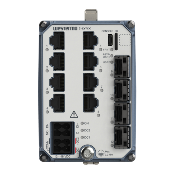
Warning symbol, see warning in Power Input and I/O Connection [13] LED indicators The base MAC address and production date of the product is included in the front label QR code Figure 3. Location of interface ports and LED indicators Lynx 5500 Series... -
Page 13: Connector Information
The console port can be used to connect to the CLI (Command Line Interface). The console connector is a micro USB cable that connects to a FTDI FT232R USB to serial converter internally. For drivers, refer to www.ftdichip.com and download the appropriate VCP driver. Lynx 5500 Series... -
Page 14: Micro Sd
Figure 5. Insertion of micro SD card 3.4.4. SFP Transceivers The product supports UL and IEC certified transceivers only. See Westermo's modular transceivers datasheets 100 Mbit and 1 Gbit for supported SFP transceivers, which can be downloaded from the product support pages at www.westermo.com/support/product-... -
Page 15: Led Indicators
USR2 Configurable, see WeOS user Guide TX/FX No link ports GREEN Link established GREEN Data traffic indication FLASH YELLOW Port alarm and no link. Or if FRNT or RSTP mode, port is blocked. Table 8. LED indicators Lynx 5500 Series... -
Page 16: Dimensions
3.6. Dimensions Dimensions are stated in mm and are regardless model. 92 (DIN surface to front) 2 to 8 2 to 8 Figure 6. Dimensional drawing Lynx 5500 Series... -
Page 17: Installation
4.2. Removal of Product To remove the product either push the support pin down and towards the front of the product, or press down the support at the back with a screwdriver, and lift off the product from the DIN-rail. Lynx 5500 Series... -
Page 18: Protective Earth Connection
Figure 8. Removal of product by pushing the support pin Figure 9. Removal of product with screwdriver 4.3. Protective Earth Connection For correct function, the earth connection needs to be properly connected to a designated PE rail. See the figure below. Torque: 3.2 Nm. Lynx 5500 Series... -
Page 19: Cooling
Figure 11. Miminum spacing of product REDUCE THE RISK OF FIRE To reduce the risk of fire, use only telecommunication line cords with a cable diameter of AWG 26 or larger. Regarding power cable dimensions, see chapter Interface Specifications. Lynx 5500 Series... -
Page 20: Specifications
For minimum temperature rating of the cable to be connected to the field wiring terminals: +90 °C Circuit type SELV Shielded cable Not required Only CE-compliant Class I or Class II power supplies with SELV/PELV output shall be used with the product Measured for 1 second at startup Lynx 5500 Series... - Page 21 TNV-1 according to IEC 62151 Transmission range Up to 100 m with CAT5e cable or better Isolation All other ports Cabling Shielded cable CAT5e or better is recommended Conductive chassis 10/100/1000 Mbit/s ports are no. 1 to 8 Lynx 5500 Series...
- Page 22 USB Micro B connector in device mode External circuits connected to I/O connectors shall be SELV-rated circuits, galvanic isolated from mains. Micro SD Electrical specification Secure Digital 2.0 Circuit type SELV Maximum supply current 100 mA Connector Micro SD connector Lynx 5500 Series...
-
Page 23: Type Tests And Environmental Conditions
DM: ±2.5 kV 200 Ω/0.5 µF, 1 MHz CM: ±2.5 kV 200 Ω/0.5 µF, 1 MHz I/O port DM: ±2.5 kV 200 Ω/0.5 µF, 1 MHz Ethernet ports CM: ±2.5 kV 200 Ω, 1 MHz, Direct on shield Lynx 5500 Series... - Page 24 I/O port to all other ports IEEE 802.3 Ethernet ports to all other ports Dielectric strength AREMA Power port (DC) 2121 VDC, 60 s to all other ports 1500 VAC rms, 60 s Lynx 5500 Series...
- Page 25 1500 VAC rms, 60 s to all other ports I/O port to all other ports IEEE 802.3 Ethernet ports to all other ports Impulse withstand IEEE 802.3 Ethernet ports to 2.4 kV all other ports Table 9. EMC and electrical conditions Lynx 5500 Series...
- Page 26 , 11 ms, 3 x 6 shocks (saw tooth) Bump Operational Class 2, 20g/16 rms, 6 x 1000 bumps 60255-21-2 Enclosure EN/IEC/UL Aluminum Fire enclosure 61010-1 Weight 690 gr Degree of protection EN 60529 Enclosure IP40 Cooling Convection Lynx 5500 Series...
- Page 27 Method 3, 21 days corresponds to Harsh Industrial Environment G3 which is defined in ANSI/ISA 17.04: 2015 The power and I/O cables need to be fastened 200 mm or closer to the unit. The same recommendation applies to the Ethernet cables. Table 10. Environmental and mechanical conditions Lynx 5500 Series...
-
Page 28: Revision Notes
2.5.4 NEMA TS2 new chapter, 5.1 Interface Specifications, DC Power port updated (cable temperature rating), 5.2 Type Tests and Environmental Conditions updated (temperature range updated). Rev. B 2020-08 Illustrations updated from brown to blue products. Rev. A 2019-12 First revision Lynx 5500 Series... - Page 29 Westermo • Metallverksgatan 6, SE-721 30 Västerås, Sweden Tel +46 16 42 80 00 Fax +46 16 42 80 01 E-mail: info@westermo.com www.westermo.com 6643-25001 REV F 2022 01 Westermo Network Technologies AB, Sweden...
Need help?
Do you have a question about the Lynx 5500 Series and is the answer not in the manual?
Questions and answers