
Related Manuals for Eliwell EWHT 1800LX


Summary of Contents for Eliwell EWHT 1800LX
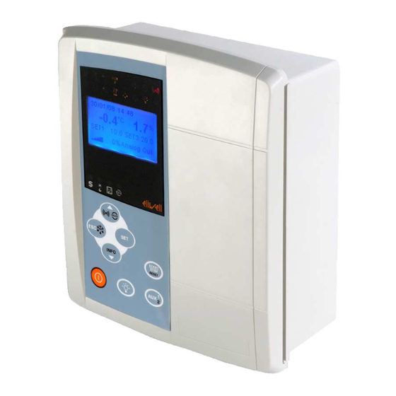
- Page 1 EWHT 1800LX Controllers for seasoning cycle cells with display for on-board installation <IMG INFO> 283,35 343,45 117,7 14,15...
-
Page 2: Table Of Contents
CONTENTS How to use this manual............................5 Introduction ................................6 General Description..................................6 Models and Features ..................................6 User interface ................................7 Keys........................................7 3.1.1 Description of keys and associated functions.................................... 9 STANDBY / OFF ....................................9 3.2.1 Description of keys - combined action...................................... 10 Display....................................... - Page 3 17.13.2 Parameters table............................................81 17.14 Client table ....................................96 18 Electrical connections ............................101 18.1 General warnings..................................101 18.1.1 Power supply - High voltage inputs (relay) ..................................101 18.1.2 Analogue inputs-Probes .........................................101 18.1.3 Serial connections ............................................102 18.1.3.1 RS485 connection ..........................................102 EWHT 1800LX 3/141...
- Page 4 27 Advanced Functions - HACCP.........................129 27.1.1 HACCP alarm messages ..........................................129 27.1.2 HACCP Power Failure Alarm (PF)......................................130 27.1.3 Deleting HACCP alarms...........................................130 28 Annexe A – Models and Accessories ......................131 28.1 Models ......................................131 28.2 Accessories.....................................132 28.2.1 All models..............................................132 29 Analitic Index ...............................139 EWHT 1800LX 4/141...
-
Page 5: How To Use This Manual
HOW TO USE THIS MANUAL This manual is designed to permit quick, easy reference with the following features: References column: References A column to the left of the text contains references to subjects discussed in the text to help you locate the information you need quickly and easily. -
Page 6: Introduction
• food storage cells (fruit, vegetables, meat) • abattoirs • dryers for wood, skins, paper, marble • Models and Features <IMG INFO> -->See Annex A - Models Accessories and the Specifications chapter 56,75 29,75 28 35 EWHT 1800LX 6/141... -
Page 7: User Interface
IMG INFO Open INFO N.A. Info Menu Quit and save new settings Esc(ape) Quit Quit Quit Quit Quit - - - IMG INFO (and save new go back to settings) previous level [Activates [DEFROST] manual defrost] EWHT 1800LX 7/141... - Page 8 (and save new Move to next level settings) (open folder, subfolder, parameter, value) *Activation time can be configured from Alarm Alarm Alarm Alarm Alarm H02 with the exception acknowledgm acknowledgm acknowledgm acknowledgm acknowledg ment SET NOT CONFIGURABLE EWHT 1800LX 8/141...
-
Page 9: Description Of Keys And Associated Functions
On, and all regulators are locked including alarms • 1157: H08= ONLY DISPLAY: the display reads “OFF”, and all regulators are locked • - including the alarms The standby regulator can also be activated via digital input, when so configured. EWHT 1800LX 9/141... -
Page 10: Description Of Keys - Combined Action
From unlocked keypad Lock keypad Shows the message LOC on the display IMG INFO simultaneously Unlock keypad From locked keypad IMG INFO display display Main Menu Main Menu Standard mode (on) screensaver mode Locked keypad Locked keypad EWHT 1800LX 10/141... -
Page 11: Display
Main Menu, standard mode (on) Main Menu, screensaver mode Automatic (climate profiles active) In standby the display mode is determined by parameter 1157: HO8: display Display (screensaver mode) Alternating Only If probe regulators faults present Display only EWHT 1800LX 11/141... -
Page 12: Leds
(Defrost) automatic active Defrost Defrost yellow automatic 1 <drip point> (Defrost active Defrost Defrost yellow automatic 2 <drip point> (Defrost active yellow Heating IMG INFO Humidification yellow Humidify active Dehumidify Dehumidification yellow active Light yellow Light on EWHT 1800LX 12/141... - Page 13 Green enabled <IMG INFO> 26,45 43,8 <Memory limited Datalogger Green Data recording (more than 95% IMG INFO memory already in use> Deep Cooling Deep cooling Cycle Green Cycle active Off in cases not described (e.g. compressor off) EWHT 1800LX 13/141...
-
Page 14: Access To Menus
Value Pb1 Probe 1 Value Pb2 Probe 2 Value Pb2 Probe 2 Value Pb3 Probe 3 Value Pb3 Probe 3 Value Pb4 Probe 4 Value Pb4 Probe 4 Value Pb5 Probe 5 Value Pb5 Probe 5 (default) EWHT 1800LX 14/141... -
Page 15: Example Of How To Set The Setpoint (Set1, Srh)
- - - If you press the SET’ or ‘ESC’ keys again, or allow the time out (15 seconds) to elapse, the new value will be saved and the display wil return to the starting screen secondary 20%RH EWHT 1800LX 15/141... -
Page 16: Info Menu
To access the Menus, press the SET key Menu Page ▼ 1 Probes 2 Date and time Time Bands Menu Page ▼▲ 4 Functions 5 Service 6 Data logger Menu Page ▲ 6 Data logger Parameters Climate Profiles EWHT 1800LX 16/141... -
Page 17: Probes Menu
Press SET again to confirm and move on to setting the month in the same way as above. The other values are set in the same way. Date and time 05/02/08 14.30 Date and time 06/02/08 14.30 EWHT 1800LX 17/141... -
Page 18: Setpoint Menu
This enters Edit Mode: the value of SET1 is highlighted: change it with the UP and DOWN keys ▲▼ Press SET again to confirm. In the same way as above, UP and DOWN ▲▼ to select and edit the value of SRH Set Point SET1 --18.0°C 35%RH Date and time SET1 --18.0°C 35%RH EWHT 1800LX 18/141... -
Page 19: Passwords
If the password is correct, the Parameters Menu opens The same procedure holds for the User level password. Passwords can be changed in the Parameters menu >Display> 1122: User Password 1123: INstaller Password EWHT 1800LX 19/141... -
Page 20: Time Bands Menu See Advanced Functions - Night And Day
Reset HACCP alarms (°) (°) The function returns to the OFF state when you exit the Functions Menu (°°)the function returns to OFF for a time 3.9.5 Service Menu - see Advanced functions - Datalogger & Service EWHT 1800LX 20/141... -
Page 21: Parameter Programming Menu
"ESC" or "SET", or wait for the 60-second timeout to elapse to save the new value set. Now press and release the Esc key to return to the previous levels viewed. To return to the Main Menu press and hold down ESC. EWHT 1800LX 21/141... -
Page 22: Datalogger Menu - See Advanced Functions - Datalogger & Service
Datalogger menu – see Advanced functions - Datalogger & Service 3.9.8 Climate Profiles menu - see Climate Profiles Climate profiles Page ▼ STEP 1 STEP 2 STEP 3 Menu Page ▼▲ STEP 4 STEP 5 STEP 6 EWHT 1800LX 22/141... -
Page 23: Input-Output Configuration
Configuration of Probe not 1182: Probe Pb3 analogue inserted configuration output) 1183: Configuration probe Pb4 External 1184: Probe Pb5 Humidity exchanger configuration probe pressure probe NOTE: // indicates that value is not present EWHT 1800LX 23/141... -
Page 24: Configuration Of Digital Inputs
+5= external alarm of digital input DI2 Configuration 1161: H13 -21…+21 See table B +9= low pressure switch of digital input DI3 Configuration 1162: H14 -21…+21 See table B +10= high pressure switch of digital input DI4 EWHT 1800LX 24/141... - Page 25 START/STOP climate profile cycle; press and hold toggle (H02) reset. If more than one parameter in the table is configured with the same value, the input with a higher index has priority - the other inputs become irrelevant. EWHT 1800LX 25/141...
-
Page 26: Configuration Of Digital Outputs - Relays
(AUX1) Programmable by parameter 1168: H26 OUT6 Digital output Stratification fans (AUX2) Programmable by parameter 1169: H27 OUT7 Digital output Light Fixed output NOT configurable OUT8 Digital output buzzer present on keyboard Fixed output NOT configurable EWHT 1800LX 26/141... -
Page 27: Configuration Of Analogue Output
KEYB - which we will also call COM1: base/keyboard comms channel TTL serial can be used for configuring parameters with the Param Manager software using the Eliwell protocol • • configuring device parameters, states, and variables with the Modbus via the Modbus protocol See the table below:... -
Page 28: Copy Card
Two types of Copy Card are available on request as accessories: item number Description Description CopyCard CopyCard CCS00A00M003 USB CopyCard Italian/English glossary CCA0BUI02M003 CopyCard Datalogger See section Advanced functions - Datalogger & Service for the Upload Download procedures EWHT 1800LX 28/141... -
Page 29: Compressors
(cold room probe failure) and of requests from other utilities (Duty Cycle mode). compressor If the cold room probe is working properly, the Duty Cycle mode does not activate as it does not have priority over normal compressor regulator settings. EWHT 1800LX 29/141... -
Page 30: Compressor Safety Times
Compressor protection diagram with parameters 1011:dOn / 1012: dOF 1013: dbi configured. Compressor diagram with Input state for compressor regulator. parameters (1011:dOn / 1012: Output state for compressor regulator. dOF / 1013: dbi) Time Time EWHT 1800LX 30/141... -
Page 31: Heating / Cooling
1156: H07 relay Disabled SET2 Heating OUT3 Heating relay Comments Temperature ≤ SET2- Temperature > SET2 1026: diH= 0 1027: db -->differential=1027: 1027: db always positive Relay HEATING diH=0 Temperature SetPoint = SET2 <IMG INFO> 226,75 174,35 99,65 EWHT 1800LX 31/141... -
Page 32: Cooling
1027: db always positive Relay COOL diF=0 Temperature SetPoint = SET1 <IMG INFO> 226,75 174,35 99,65 Neutral Zone Set type of temperature regulation 1156: H07=Neutral Zone • Setpoint 1156: H07 relay relay Disabled SET1 Neutral zone OUT3 OUT4 EWHT 1800LX 32/141... -
Page 33: Heating/Cooling
OUT3 ±20 Heating/Cooling Example 1159:H11= ±20 Heating/Cooling Contact open [D.I. open] :cooling Contact closed [D.I.closed]: heating <IMG INFO> 339,15 362,75 71,15 relay set as cooling (OUT3 FREDDO = COOLING) relay set as heating (OUT4 CALDO = HEATING) EWHT 1800LX 33/141... -
Page 34: Defrost
If the internal exchanger probe temperature is greater than 1034: dSt, defrost will not be permitted: a new interval will be counted and only at the end of this subsequent count will conditions be tested for the start of a defrost cycle EWHT 1800LX 34/141... -
Page 35: Automatic Defrost With Real Time Clock
Digital Input. procedures from Output state for defrost regulator. Digital Input Note: (1034: dSt) indicates end defrost time when temperature reached. Time Time (dSt) Time Time (dSt) (dSt) IMG INFO Time Time (dSt) (dSt) IMG INFO EWHT 1800LX 35/141... -
Page 36: Defrost Modes
See Electrical Heaters for defrost section. The heaters are switched off on completion of the defrost cycle. During dripping, the compressor continues to thermo regulate. Defrost ends in the same way as the previous case. EWHT 1800LX 36/141... -
Page 37: Defrost Mode Diagrams
Off if parameter 1045: dFd is set accordingly, otherwise the other they will behave as set for the fan regulator. DEFROST WITH ELECTRICAL HEATERS Start Defrost Time Time (dSt) Time <IMG INFO> Defrost with electrical heaters diagram EWHT 1800LX 37/141... - Page 38 • parameter 1136: Ldd (Lock defrost disable). IMPORTANT: the display will nevertheless be unlocked after dripping as if it has been configured, it locks regulators. EWHT 1800LX 38/141...
-
Page 39: Fans
(block fans temperature) and 1042: FAd (fans differential). The block fans temperature set in parameter FSt is absolute (real temperature value) The fan regulator functions as indicated below: Diagram: block fans at absolute temperature with Temp. Temp. EWHT 1800LX 39/141... -
Page 40: Ventilation Fans (Ewht800Lx)
Operation is cyclical based on parameters 1072: Con 1073: COF. 1072: COn 1073: COF >0 >0 >0 >0 Duty cycle Fans are off: As in the table. • • When the device is Off (local or remote). • Power failure. EWHT 1800LX 40/141... -
Page 41: External Exchanger Fans
Condenser fans do not function: • When the device is Off (local or remote) • one or more alarms block the recirculation fan EWHT 1800LX 41/141... -
Page 42: Continuous Operation
*COOL *HEAT diagrams for fan speed based on the regulation probe COOL diagram A Speed (%) Temp/Press. <IMG INFO> HEAT diagram B Speed (%) Temp/Press Temp: External exchanger temperature Press.: External exchanger pressure EWHT 1800LX 42/141... -
Page 43: Operation On Call
Operation on call 10.1.2 Operation on call Diagram C Diagram D Cooling Heating Relay Set Point F09 Relay Set Point F09 Temp. Temp. <IMG INFO> EWHT 1800LX 43/141... -
Page 44: Stratification Fans (Ewht800Lx)
If the cold store probe is located high up, the stratification probe should be positioned low down, and vice versa. Stratification probe error 1182: H43=4 or 1077: SOn 1078: SOF 1183: H44=4 Relay Temp. Pb1-Pb3 = SFd - diS Pb1-Pb3 > SFd <IMG INFO> EWHT 1800LX 44/141... -
Page 45: Deep Cooling Cycle
If parameters 1016: dcS, 1017: tdc and 1018: ddc are modified, the Deep Cooling Cycle is recalculated with the new values set. End defrost (dSt) temperature set DCC DCC timeout defrost timeout par.tcd compressor defrost EWHT 1800LX 45/141... -
Page 46: Pressure Switch And Preheating
Preheat Input Regulator The digital input configured as Preheat (1159: H11..1162: H14 =12) disables compressor and fan outputs. When the preheat input is activated, this is not indicated on the display but in the Alarms folder EWHT 1800LX 46/141... -
Page 47: Humidity
Humidify relay N.B. Humidity = SRH- Humidity > SRH dFH= 0 1021: dbH -->differential = 1021: dbH 1021: dbH always positive Relay UMIDIFICA dFH=0 Umidity SetPoint = SRH <IMG INFO> 226,75 185,85 99,1 UMIDIFICA = HUMIDIFY EWHT 1800LX 47/141... -
Page 48: Dehumidify
Umidity SetPoint = SRH <IMG INFO> 226,75 185,85 -999998 4,95 Relay Relay DEUMIDIFICA + COOL DEUMIDIFICA dFH=0 dFH=0 Umidity Umidity SetPoint = SRH <IMG INFO> 226,75 185,85 -999998 0,05 SetPoint = SRH <IMG INFO> 226,75 185,85 99,1 EWHT 1800LX 48/141... -
Page 49: Neutral Zone
14.1.3 Neutral zone To regulate humidity in the Neutral Zone, set 1154: H05= Neutral Zone (nE) See cases B-D illustrated above. EWHT 1800LX 49/141... -
Page 50: Climate Profiles
28/02/08 10:32 -18.3°C 35%RH STEP 1: START 18 : - - press SET again and set the STEP start minutes with the UP and DOWN keys 28/02/08 10:33 -18.3°C 35%RH STEP 1: START 18 : 00 EWHT 1800LX 50/141... - Page 51 STOP STEP: 3 STOP 04: 00 Stopped manually STOP STEP 3 STOP STEP: 3 STOP 00: 00 RESET No profile active STEP 1 START 01: 00 STEP: 3 STOP 00: 00 End of cycle Step 3 ended EWHT 1800LX 51/141...
-
Page 52: Description Of Steps / Parameters
For activation instructions, see (°) P1 Step duration Defines the duration of the step. In hours and minutes [HH: mm] If = 00.00 indicates the end of the step when temperature is reached and not on time elapsed EWHT 1800LX 52/141... - Page 53 * value has no effect during STEP8 - there are no further steps P9 GO BACK TO STEP NO.xx STEP number to go back to Defines which STEP to return to if P8 is set to Step EWHT 1800LX 53/141...
-
Page 54: Step Parameters Table
Type of regulator active TEMPERATURE Type of regulator active TEMPERATURE HUMIDITY SETPOINT TEMPERATURE Dynamic visibility SETPOINT based on value No. COOL TEMPERATURE Dynamic visibility SETPOINT based on value No. HEAT ENABLING AUX RELAY GO BACK TO STEP NO.xx EWHT 1800LX 54/141... -
Page 55: Example
STEP1 DELAY 1 ZN / ZN Humidity temperature A Endurance Set Point Set Point STEP2 ZN / ZN Humidity temperature B Endurance Set Point SetPoint t STEP3 ZN / ZN Humidity emperature A <IMG INFO> 339 15 EWHT 1800LX 55/141... -
Page 56: Alarms And Troubleshooting
Analogous to E1 • Display Analogous to E1 faulty Alarms Menu “E4” label • shown on display; (screensaver mode only) See F20 • E5 (!) (§) Humidity probe faulty Analogous to E1 • Display Analogous to E1 EWHT 1800LX 56/141... - Page 57 (§) Depending on configuration of parameters H41 H42 H43…H45 (the table gives the default values highlighted with (§)) the error displayed E3 E4 E5 indicates the type of probe failure. Example: E3 indicates a stratification probe fault. EWHT 1800LX 57/141...
-
Page 58: Alarms
1090: LHA External alarm • due to activation of • Logging the • Manual silencing 01 External alarm the digital input label in the of buzzer after the delay Alarms Menu The controllers • EWHT 1800LX 58/141... -
Page 59: High/Low Temperature And Humidity Alarms
1081: HAL …1082: LAL Probe 3 alarm 1081: HAL …1082: LAL Probe 1 and 3 alarm 1081: HAL …1082: LAL (same for both probes) Probe 1 and 3 alarm 1081: HAL …1082: LAL (probe 1) and 1100: SA3 (probe 3) EWHT 1800LX 59/141... -
Page 60: High/Low Temperature Alarm Exclusion Times
Using parameter 1085: tAO you can set a delay for the signalling of the alarm after defrosting. time after defrost This parameter refers to high/low temperature alarms only During this interval, the regulator is disabled and any temperature alarms are not signalled. EWHT 1800LX 60/141... -
Page 61: High/Low Humidity Alarm Exclusion Times
1088: AtH 1088: AtH Temp. Temp. Temp. Temp. SRH + LHA SRH + HHA AFD --> 1080: AFD HAL --> 1081: HAL LAL --> 1082: LAL HHA --> 1089: HHA LHA --> 1090: LHA ADH --> 1091: ADH EWHT 1800LX 61/141... - Page 62 [Setpoint + LAL] equals [Setpoint - LAL] if Att=reL(ative) LHA must be negative humidity so [Setpoint + LHA] equals [Setpoint - LHA] Notice: during a defrost cycle, high and low temperature alarms are excluded. IMG INFO EWHT 1800LX 62/141...
-
Page 63: Parameters
PARAMETERS parameters can be set to fully configure the EWHT 1800LX; They can be modified with: the instrument’s keyboard • To access the Parameters Menu and protect the parameters by setting a password, see the User Interface chapter Personal computer using Param Manager •... -
Page 64: Compressor (File With Label "Compressor")
Function section Related parameters: 1150: H01, 1029: dit 1016: dCS Deep Cooling Cycle Setpoint Deep cooling cycle set point 1017: tdc Duration of the deep cooling cycle 1018: dcc Defrost delay after deep cooling cycle In minutes. EWHT 1800LX 64/141... -
Page 65: Humidity(File With Label "Humidity")
= A defrost cycle is run at each compressor stop, depending on the parameter 1028: dty • • (3) Clock = Defrost at times set in the Time Bands EWHT 1800LX 65/141... - Page 66 Pag ▼▲ 4 Functions 5 Service 6 Data logger To access the defrost times menu, press the SET key Time slots Defrost time To access Weekdays Menu, press the SET key Defrost time. Working D. Week End EWHT 1800LX 66/141...
- Page 67 24, this indicates that the parameter is deactivated. • Notice Hours: (Range defrost times> weekdays / weekends= 0…24, 24= parameter deactivated) • • Minutes (Range defrost times> weekdays / weekends= 0…59, 59= parameter deactivated) EWHT 1800LX 67/141...
-
Page 68: Fans (Folder Labeled "Evaporator Fan")
Selects fan deactivation when the door is opened and fan restart when the door is shut (if they were running) • fans off= fans stopped; (1) Unchanged= fan status unchanged; • 1048: FdC Fans OFF delay Fan switch off delay after compressor stop. In minutes. 0= function excluded EWHT 1800LX 68/141... -
Page 69: Analogue Output (File Labelled "Analogue Output")
Bypass time for external exchanger fan cut-off 1070: F19 External exchanger fan preventilation time in Heat/Cool 1071: F20 Fan state during regulation probe error • (0) off = fan off (OFF) (1) on = fan on (ON) • EWHT 1800LX 69/141... -
Page 70: Ventilation Fans (File Labeled "Ventilation Fans")
1076: diS Stratification Fan(s) differential Temperature differential for stratification fans 1077: SOn Stratification Fan(s) On ON time for stratification fan regulator output* 1078: SOF Stratification Fan(s) OFF OFF time for stratification fan regulator output* *In minutes EWHT 1800LX 70/141... -
Page 71: Alarms (File Labelled "Alarms")
Related parameters: 1089: HHA, 1090: LHA 1089:HHA Maximum humidity alarm threshold Humidity value (distance from setpoint or absolute value in relation to Att), which when exceeded triggers an alarm signal. See Max/Min. Alarm Diagram. Related parameters: 1088: AtH, 1090: LHA EWHT 1800LX 71/141... - Page 72 3 • • (1) All probes = alarm relay enabled for alarms/errors regarding all probes (2) Probe 3 only= alarm relay enabled ONLY for alarms/errors regarding probe 3 • EWHT 1800LX 72/141...
-
Page 73: Light And Digital Inputs (File With Label "Light And Digital Input")
The pair of values FAA and dEA represents the network address of the device and is indicated in the format "FF.DD" (where FF=FAA and DD=dEA) 1120: PtY ParitY bit Modbus Modbus parity bit: • (0) None (1) Even • • (2) Odd EWHT 1800LX 73/141... -
Page 74: Display (File With Label "Display")
Value to be shown on main display (1)= probe 1 (2)= probe 2 (3)= probe 3 (4) = probe 4; (5) = probe 5; 1139: dd2 default display Value to be shown on secondary display Analogous to 1138: ddd EWHT 1800LX 74/141... -
Page 75: Haccp Alarm Parameters (Folder With Label "Haccp")
NOT enabled • 3=HACCP alarms enabled with alarm relay enabled 1147: H51 Time HACCP alarm recording is excluded (key or D.I.) 1148: H52 Probe enabled to signal HACCP alarms: 1=Probe 1 • • 3=Probe 3 EWHT 1800LX 75/141... -
Page 76: Configuration Parameters (File With Label "Configuration")
Activate light relay ±15 Activate ventilation fan relay ±16 Enable/disable night & day functions ±17 deep cooling cycle ±18 Panic alarm ±19 Reset HACCP alarms ±20 heating/cooling mode ±21 START/STOP climate profile cycle; press and hold (H02) reset. EWHT 1800LX 76/141... - Page 77 1183: H44 Probe configuration Pb4 Analogous to 1180:H41 1184: H45 Probe Pb5 configuration = probe not present humidity Probe = exchanger pressure probe 1186: H48 Clock present (RTC) • (0) n= not present; • (1) y= present; EWHT 1800LX 77/141...
-
Page 78: 17.13 Parameters/Client Table
Same as above. In this case, the parameter visibility value is in the MODBUS register address. By default, all parameters have: • DATA SIZE 2 bit • Range 0…3 • U.M. number Visibility 0…3 • 0 = parameter not visible EWHT 1800LX 78/141... - Page 79 The value read from the register is 500 --> 500/10 = 50.0 • U.M. Units of Measure of values WHEN UTILIZING MODBUS PROTOCOL ONLY Measurement unit for values converted according to the rules indicated in the columns. EWHT 1800LX 79/141...
-
Page 80: See Reference Guide
24/24 RH (humidity) alarms N.A. ● 5/24 Light and digital input Light N.A. ● 12/12 12/12 Communication Serial addressing N.A. ● Display display ● ● 16/16 16/16 HACCP HACCP N.A. ● Configuration Configuration N.A. ● 19/19 19/19 EWHT 1800LX 80/141... -
Page 81: Parameters Table
49287 ore/min/ USr/InS 1189 WORD 1 ... 255 Def.stop temp.evap1 USr/InS 1034 16398 RW WORD Y -302.0 ... 1472.0 -1 °C/°F Def.counting type USr/InS 1036 49289 RW WORD n/y [0 ... 1] n [0] flag Def.power ON EWHT 1800LX 81/141... - Page 82 Start time for defrost nr. 1 during Time slots Usr/InS Defrost F1_ore WORD 0 … 24 holidays Defrost time Week 49426 Start minutes for defrost nr. 1 during Time slots Usr/InS Defrost F1_min WORD 0 … 59 holidays EWHT 1800LX 82/141...
- Page 83 Start time for defrost nr. 8 during Time slots Usr/InS Defrost F8_ore WORD 0 … 24 holidays Defrost time Week 49440 Start minutes for defrost nr. 8 during Time slots Usr/InS Defrost F8_min WORD 0 … 59 holidays EWHT 1800LX 83/141...
- Page 84 1069 WORD 0 ... 255 Bypass Time USr/InS 1070 49406 WORD 0 ... 255 Pre ventilation 49407 USr/InS 1071 WORD 0 ... 1 Cond. Fan: Probe KO 49379 USr/InS 1072 WORD 0 ... 255 Change fan ON EWHT 1800LX 84/141...
- Page 85 P8 End Step prof. RW End step 1 of program 1 WORD 1 … 6 Thermal STEP1 49936 P9 Jump to prof. RW Number of partial cycle to run for step 1 of program 1 WORD 0 … 7 EWHT 1800LX 85/141...
- Page 86 49959 diS/nE/H/C/dEH P3 Temp.reg. prof. RW Regulator active for step 3 of program 1 WORD [0 … 4] STEP 3 17192 Thermal P4 Set RH WORD LSH …HSH -1 °R Humidity setpoint SP3 step 3 program 1 EWHT 1800LX 86/141...
- Page 87 RW Number of partial cycle to run for step 4 of program 1 WORD 0 … 7 Thermal STEP 5 49986 P0 Delay prof. 5P0_H RW Activation delay step 5 program 1 WORD 0 … 99 EWHT 1800LX 87/141...
- Page 88 STEP 6 17240 P4 Set RH prof. WORD LSH …HSH -1 °R Humidity setpoint SP3 step 6 program 1 STEP 6 17242 Thermal P5 Set 1 WORD LSE …HSE -1 °C/°F Humidity setpoint SP1 step 6 program 1 EWHT 1800LX 88/141...
- Page 89 STEP 8 50034 P0 Delay prof. 8P0_H RW Activation delay step 8 program 1 WORD 0 … 99 Thermal STEP 8 50035 P0 Delay prof. 8P0_M RW Activation delay step 8 program 1 WORD 0 … 59 EWHT 1800LX 89/141...
- Page 90 49304 USr/InS 1084 WORD 0 ... 999 Defrost alarm over. 1085 49305 WORD 0 ... 10 No Alarm 49306 1086 WORD 0 ... 255 Timeout door open 49307 USr/InS 1087 WORD 0 ... 255 Temp alarm override EWHT 1800LX 90/141...
- Page 91 Enable forced by DI 49324 1113 WORD 0 ... 255 Delay on Compressor 1114 49325 WORD 0 ... 255 Delay on FAN 49326 1115 WORD 0 ... 15 N°press.switch act. 49327 1116 WORD 1 ... 99 Switch err interval EWHT 1800LX 91/141...
- Page 92 Time slots d6 Friday d5_E03 WORD 0 … 1 flag E0 Event Enable weekday/holiday defrost of day 6 49447 Time slots Time slots d7 Saturday E0 Event d6_E00 Enable functions during events day 7 WORD 0 … 4 EWHT 1800LX 92/141...
- Page 93 0 ... 999 Password inst. 1123 PA2 [PW1_3] 49490 WORD 0 ... 999 Password inst. 1123 PA2 [PW1_4] 49491 WORD 0 ... 999 Password inst. 49333 USr/InS 1124 WORD n/y [0 ... 1] flag Number display type EWHT 1800LX 93/141...
- Page 94 °R Upper limit V/I AI 49348 diS/nE/HU/dEH 1154 WORD [0 ... 3] Type of Hum. reg. 49349 1155 WORD n/y [0 ... 1] flag DI AUX Key 49350 diS/nE/H/C/dEH 1156 WORD [0 ... 4] Type of temp.reg. EWHT 1800LX 94/141...
- Page 95 WORD 0 ... 4 Config. probe 3 49373 1183 WORD 0 ... 4 Config. probe 4 1184 49374 WORD 0 ... 2 Config. probe 5 49376 1186 WORD n/y [0 ... 1] Y [1] flag RTC present EWHT 1800LX 95/141...
-
Page 96: 17.14 Client Table
High analogue input threshold exceeded 3 33367,4 1 bit 0 ... 1 flag Low analogue input threshold exceeded 3 33367,5 1 bit 0 ... 1 flag Time lost alarm 33367,6 1 bit 0 ... 1 flag EWHT 1800LX 96/141... - Page 97 33032 1 bit 0 ... 1 Disable Night & Day functions CMD_DIS_NIGHTDAY_OFF 33032,1 1 bit 0 ... 1 Alarm silencing CMD_TACITA 33032,2 1 bit 0 ... 1 Manual defrost activation CMD_DEFROST 33032,3 1 bit 0 ... 1 EWHT 1800LX 97/141...
- Page 98 0 ... 1 flag Defrost 33165,2 Relay FAN EVAP 1 bit 0 ... 1 flag Evaporator fan command output 33165,3 Relay ALARM 1 bit 0 ... 1 flag Alarm 33165,4 Relay AUX 1 bit 0 ... 1 flag EWHT 1800LX 98/141...
- Page 99 Secondi* 33344 Minuti* 33345 Ore* 33347 Giorno* 33346 Giorno della settimana* 33347 Mese* 33348 Anno* *To change proceed as follows: load the televis 261 timeout • • set the values from 33343 to 33348 • Write 33032,4 EWHT 1800LX 99/141...
- Page 100 EWHT 1800LX 100/141...
-
Page 101: Electrical Connections
Humidity probes have a specific insertion polarity which must be observed. Signal cables (temperature/pressure probes, digital inputs, serial) must be cabled separately from high voltage cables. Eliwell supplied cables are recommended. Contact Eliwell sales department for item availability. EWHT 1800LX 101/141... -
Page 102: Serial Connections
18.1.3.2 TTL connection a 5-wire cable up to 30cm in length. An Eliwell-supplied cable is recommended. Contact Eliwell sales department for item availability. Notice: using the TTL serial for ParamManager via PCInterface interferes with the readings of analogue input AI5. -
Page 103: Circuit Diagrams
HEATING 27-28 OUT2 NA 8(3) SPST 250V~ HUMIDIFY Humidify 29-30 OUT1 NA 8(3) SPST 250V~ DE-HUMIDIFY Dehumidify Power Supply 31-32 POWER SUPPLY Power Supply 95…240V~ Power supply 95…240V~ Power supply * configure as defrost relay if required EWHT 1800LX 103/141... - Page 104 Cabinet Probe Digital Inputs 64-65 D.I. 1 High Pressure NO Max. Pressure 66-67 D.I. 2 Low Pressure NO Min. Pressure Digital inputs 68-69 D.I. 3 Alarm NO External alarm 70-71 D.I. 4 Door switch NO Door switch EWHT 1800LX 104/141...
-
Page 105: Circuit Diagrams
18.2.1 Circuit diagrams EWHT1800LX EWHT 1800LX 105/141... -
Page 106: Connections With Pressure/Humidity Probe Transducers
18.2.2 Connections with pressure/humidity probe transducers EWHT 1800LX 106/141... -
Page 107: Mechanical Assembly
A-B Insert the Copy Card (figure C) or the USB CopyCard (figure D) on the side in its slot and EWHT 1800LX 107/141... - Page 108 On completion, remove the Copy Card close the cap by pressing it into place. FIGURE A FIGURE B FIGURE C FIGURE D EWHT 1800LX 108/141...
-
Page 109: Technical Specifications
DI1 DI2 Digital inputs inputs DI3 DI4 Low voltage (SELV) 1 configurable output analogue outputs table A table A 4 NTC temperature intputs Analogue inputs See table B 1 4...20 mA current input 1 0-10V current inputs EWHT 1800LX 109/141... -
Page 110: Mechanical Specifications
Bayblend FR110 20.4 Display and LEDS display Display LCD graphic display 64x128px LEDS LEDs Keys keys 20.5 Serial Copy Copy Card CCA0BUI02M003 Card Copy Card CC0S00A00M003 TTL serial RS-485 Via optional module KP250110 RS485 CARD EWRCV1.0 Keyboard EWHT 1800LX 110/141... -
Page 111: Mechanical Dimensions
20.6 Mechanical dimensions Length (L) Depth (d) Height (H) Front panel (+0.2mm) Space required Hole centre distance for wall- 196.5 181,0 (+0.2mm mounting 0.1mm) EWHT 1800LX 111/141... -
Page 112: Use
(minutes) <=30 • temperature probe value logging with NTC / humidity probes with 4..20mA / 0-10V signals, Eliwell NOTE: We recommend downloading data only when the logging function is NOT ACTIVE. Otherwise, the download will include the most recent logged event. -
Page 113: Liability And Residual Risks
This document is exclusive property of Eliwell Controls srl. and cannot be reproduced and circulated unless expressly authorized by Eliwell Controls srl Although all possible measures have been taken by Eliwell Controls srl l. to guarantee the accuracy of this document, it does not accept any responsibility arising out of its use. -
Page 114: Advanced Functions - Datalogger & Service
If the CopyCard is not connected, the screen displays Service No CopyCard Delete Glossaries Change Glossary If the CopyCard is properly connected, the display Service Page ▼▲ Download Map. .map Download glo. .glo Upload Mappa .map Service Page ▲ Upload .map Delete Glossaries Change Glossary EWHT 1800LX 114/141... - Page 115 NOTE: The name must be of max 8 alphanumeric characters The following screen displays. Wait a few seconds for the operation to complete Download Running If the download terminates successfully, the following screen displays: Download Otherwise, the following message displays Download Error EWHT 1800LX 115/141...
-
Page 116: Glossaries
Otherwise, the following message displays Upload Error 25.2 Glossaries All menus can display as standard in Italian and English Check the availability of your local language with the Eliwell Sales Department. 25.2.1 Delete Glossaries IMPORTANT: QUALIFIED STAFF ONLY! Service Page ▲ Upload .map... -
Page 117: Change Glossary
SEARCH GLOSSARY Select the desired menu language by selecting it in this menu with the UP and DOWN keys pressing SET Glossaries 01_004: Italian 02_004: English Notice: 01_ indicates the glossary language _003 indicates the glossary release EWHT 1800LX 117/141... -
Page 118: 6 Data Logger
Menu Page ▼ 1 Probes 2 Date and time Time Bands Menu Page ▼▲ 4 Functions 5 Service 6 Data logger Datalogger Page ▼ Temperatures log Alarms log States Datalogger Page ▲ Alarms log States System status EWHT 1800LX 118/141... -
Page 119: Temperatures Log
You can also [Upload] the logged data. Notice: This requires the USB CopyCard to be connected If the CopyCard is not connected, the following screen displays: Upload Errore If there are no data to upload, the following screen displays: Upload No Data EWHT 1800LX 119/141... - Page 120 25.6°C 25.7°C FAULT 05/02/2008 16.46 NORMAL FAULT FAULT 25.6°C 25.7°C FAULT LEGEND [PF] = Power Failure • [NORMAL] = normal operation • [START] = start of PF [END] = end of PF • [FAULT] = probe error EWHT 1800LX 120/141...
-
Page 121: Alarms Log
… 05/02/2008 16.43 NORMAL OFF OFF OFF OFF OFF OFF OFF OFF OFF OFF OFF OFF OFF … OFF OFF 05/02/2008 16.44 NORMAL OFF OFF OFF OFF OFF OFF OFF OFF OFF OFF OFF OFF OFF … EWHT 1800LX 121/141... -
Page 122: States
USB Copycard (°)[Device name] [date and time].STS containing the logged data. Example: DEEP DATE TIME ECONOMY NIGHT&DAY EVAPORATOR CONDENSER COOL HEATER HUMIDIFIER DEHUMIDIFIER COMPRESSOR LIGHT STAND-BY REPLACER STRATIF. DEFROST 05/02/2008 15.00 NORMAL 05/02/2008 15.01 NORMAL 05/02/2008 15.02 NORMAL EWHT 1800LX 122/141... -
Page 123: System
FAULT … FAULT … … 69.9 … 05/02/2008 17.34 NORMAL FAULT … FAULT … … 69.9 … 05/02/2008 17.35 NORMAL FAULT … FAULT … … 69.9 … 05/02/2008 17.36 NORMAL FAULT … FAULT … … 69.9 … EWHT 1800LX 123/141... - Page 124 EWHT 1800LX 124/141...
-
Page 125: Advanced Functions - Time Bands
Press SET again to confirm and move on to setting the minutes in the same way as for the hours. The other values are set in the same way. Weekdays Page ▼ Defrost 12:00 Defrost 00:00 Defrost 00:00 EWHT 1800LX 125/141... -
Page 126: Time Bands
Press SET again to confirm. The other values can be modified in the same way d1 Sunday Page ▼ E0 Event Disable E1 Start 00:00 E2 Duration d1 Sunday Page ▼ E1 Start 00:00 E2 Duration Defrost Weekdays EWHT 1800LX 126/141... - Page 127 (Tuesday = weekday) d3 > E3 = weekday (Wednesday = weekday) • d4 > E3 = weekday (Thursday = weekday) • d5 > E3 = weekday (Friday = weekday) • • d6 > E3 = weekday (Saturday = weekday) EWHT 1800LX 127/141...
- Page 128 If it occurs after this event, the device starts in the state set by the manual event. It if occurs after this event but during the activation period of the next day/night event, the controller switches to the state requested by the day/night event concerned before disabling the event at the programmed time. EWHT 1800LX 128/141...
-
Page 129: Advanced Functions - Haccp
Parameters 1143: HACCP Alarm SLH and 11442: When a temperature value exceeds the range defined by parameters 1143: SLH and 11442: SHH for a time greater than 1144: drA, a HACCP alarm is signalled and displayed. EWHT 1800LX 129/141... -
Page 130: Haccp Power Failure Alarm (Pf)
• condition is signalled by the message OW (Overwrite) in the folder of the alarm which has been overwritten. HIGH TEMPERATURE ALARM START 02/03/08 15:32 DURATION 00:32 max. temp 02/03/08 15:55 EWHT 1800LX 130/141... -
Page 131: Annexe A - Models And Accessories
ANNEXE A – MODELS AND ACCESSORIES 28.1 Models (DI1…DI4) (OUT1…OUT8) (A0) (Pb1…Pb5) EWHT 1800 LX HTFE48DTU1GH00 EWHT 1800LX 131/141... -
Page 132: Accessories
Pressure transducer TD200107 EWPA 007 4...20mA -5/8bar Male connector Pressure transducer TD300008 EWPA 007 4...20mA -5/8bar Female connector Eliwell can also supply a variety of different NTC probes depending on the cable type (PVC or silicon) and length. EWHT 1800LX 132/141... - Page 133 SWZ00000003 ABB OXS5X85 RS485 RS485 KP250110 RS485 EWRC V1.0 Name Part number Description Copy Card Smart key Copy Card CCS00A00M003 upload/download parameters Smart key • uploading/downloading USB CopyCard CCA0BUI02N000 parameters • download glossaries upload datalogger • information EWHT 1800LX 133/141...
- Page 134 PC Interface and the EWHT/EWRC device. Fan modules Name Part number Description Documentation Instruction sheet For part numbers 8FI40014 Single-phase speed regulators for CFS FAN MODULES ( See instruction sheet CFS –Fan Speed currents from 2A to 9A Modules GB-I-E-D-F EWHT 1800LX 134/141...
- Page 135 TRIAC 5+5A 230V CFS05 - TANDEM - CFS05 TANDEM FAN MODULE MW991012 Fan Speed Module GB-I-E-D-F THREE-PHASE FAN REGULATOR (DRV 300) ( Specifications: Contact Eliwell sales 3 phases 12…20A/420V~ LD312420T1S00 • 20A, 420V ~ rated; department (IP22 or IP55) Box: IP22.
- Page 136 SN560000 (range 20%...90%) Relative humidity transducer EWHS 300 SN520000 (range 5%...98%) Relative humidity (range 20%...90%) EWHS 310 SN51000 and temperature (Range -10°C…+70°C) transducer ) Various items available. Contact our Sales Office. ) Various lengths can be requested. EWHT 1800LX 136/141...
- Page 137 EWHT 1800LX 137/141...
- Page 138 EWHT 1800LX 138/141...
-
Page 139: Analitic Index
Compressor protection in the event of a probe Delay on timing ..............28 failure and Duty Cycle:1009: Ont and 1010:Oft Delete Glossaries............114 parameters ..............27 Deleting HACCP alarms ..........128 Description of keys - combined action....8 EWHT 1800LX 139/141... - Page 140 High/low humidity alarm exclusion times ....59 Parameters table ............79 High/low temperature alarm exclusion times..58 Parameters/Client Table ..........76 High/low temperature and humidity alarm Passwords.................17 conditions..............59 Phase shift ..............39 High/low temperature and humidity alarms ..57 Pick-up ................39 EWHT 1800LX 140/141...
- Page 141 Service............... 18 USER INTERFACE............... 5 SetPoint Menu ..............16 Using the Copy Card..........112 STANDBY / OFF ..............7 VENTILATION FANS (EWHT800LX) ......38 States ................120 VENTILATION FANS (file labeled ......68 STEP parameters table ..........52 STRATIFICATION FANS (EWHT800LX) ...... 42 EWHT 1800LX 141/141...
- Page 142 Facsimile +39 0437 989 066 Sales: +39 0437 986 100 (Italy) +39 0437 986 200 (other countries) saleseliwell@invensyscontrols.com Technical helpline: +39 0437 986 300 E-mail techsuppeliwell@invensyscontrols.com www.eliwell.it EWHT 1800LX 2008/04/ Cod: 8MA10214 © Eliwell Controls s.r.l. 2008 All rights reserved. EWHT 1800LX 142/141...
Need help?
Do you have a question about the EWHT 1800LX and is the answer not in the manual?
Questions and answers