Table of Contents
Advertisement
Advertisement
Table of Contents

Subscribe to Our Youtube Channel
Related Manuals for Eliwell EW961


Summary of Contents for Eliwell EW961
- Page 1 ENGLISH EW961/971/974 Electronic controllers for refrigeration units...
-
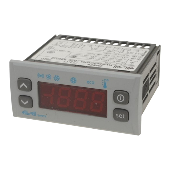
Page 2: Keys And Leds
ENGLISH KEYS AND LEDs SET / Reduced SET LED Press and release Flashing: reduced set active Scrolls through menu items Quick flashing: access to level 2 parameters Increases values Off: otherwise Press for at least 5 secs Activates the Manual Defrost function DOWN Compressor LED Press and release... -
Page 3: Accessing And Using The Menus
ACCESSING AND USING THE MENUS Resources are organised into 2 menus which are accessed as explained below: • ‘Machine Status’ menu: press and release the key. • ‘Programming’ menu: press for at least 5 secs the key. Either do not press any keys for 15 seconds (time-out) or press the key once, to confirm the last value displayed and return to the previous screen. -
Page 4: Programming Menu
PROGRAMMING MENU To access the ‘Programming’ menu press for at least 5 secs the key. If specified, the ‘PA1’ access PASSWORD will be requested (see ‘PASSWORD’ paragraph). At the access, the display will show the first parameter (“diF”). By pressing the keys you can scroll all parameters in the Programming menu: 5 secs Select the desired parameter using the... - Page 5 ALARMS Label Fault Cause Effects Remedy • Display label E1 • reading of out of range operating • Alarm icon permanently ON • check probe type (NTC) Probe1 faulty values • Min/max alarm regulator disabled • check the probe wiring (cold room) •...
-
Page 6: Manual Defrost Cycle Activation
5 seconds. If the defrost conditions are not satisfied: - the parameter OdO ≠ 0 (EW961, EW971 and EW974) - the evaporator probe Pb2 temperature is higher than the defrost end temperature (EW971 and EW974) the display will flash 3 times, to indicate that the operation will not be carried out. -
Page 7: Using The Copy Card
USING THE COPY CARD The Copy Card is an accessory connected to the TTL serial port used for quick programming of the device para- meters (upload and download a parameter map to one or more devices of the same type). Upload (label UL) and copy card formatting (label Fr) operations should be performed as explained below: After the password ‘PA2’... - Page 8 MAX AND MIN TEMPERATURE ALARM Relative Temperature Absolute Temperature Value to setpoint (Att=1) Value (Att=0) Setpoint HAL - AFd LAL + AFd Setpoint - LAL Setpoint + HAL Setpoint - LAL + AFd Setpoint + HAL - AFd Minimum temperature Temp.
-
Page 9: Electrical Wiring
- installation/use on boards that do not comply with the standards and regulations in force. DISCLAIMER This manual and its contents remain the sole property of ELIWELL CONTROLS SRL, and shall not be reproduced or distributed without authorization by ELIWELL CONTROLS SRL. -
Page 10: Conditions Of Use
CONDITIONS OF USE Permitted use For safety reasons the instrument must be installed and used according to the instruction provided and in parti- cular, under normal conditions, parts bearing dangerous voltage levels must not be accessible. The device must be adequately protected from water and dust as per the application and must also only be accessible via the use of tools (with the exception of the frontlet). -
Page 11: Further Informations
EW974: 2 NTC inputs Digital Input: 1 voltage-free digital input Output Characteristics Digital Output: EW961: 1 Compressor relay: UL60730 (A) 1,5 Hp (10FLA - 60LRA) max 250Vac or UL60730 (A) 2 Hp (12FLA - 72LRA) max 250Vac or UL60730 (A) 12A max 250Vac EW971: 1 Defrost relay: N.O. - Page 12 - cliamate range A - measurement class 1 in the range from -35°C to 25°C (*) (* exclusively using Eliwell NTC probes) NOTE: The technical data included in this document, related to measurement (range, accuracy, resolution, etc.) refer to the instrument itself, and not to its equipment such as, for example, sensors. This means, for example, that...
- Page 13 TABLE OF PARAMETERS Liv. DESCRIPTION Temperature SEtpoint. COMPRESSOR 1&2 diFferential. Relay compressor tripping differential. The compressor stops on reaching the Setpoint value (as indicated by the adjustment probe), and restarts at temperature value equal to the Setpoint plus the value of the differential. Note: the value 0 cannot be assumed 1&2 Higher SEt.
-
Page 14: Evaporator Fan
DEFROST 1&2 defrost type. Type of defrosting. 0 = electric defrost - compressor off (OFF) during defrosting; 1 = reverse cycle defrost (hot gas); compressor on (ON) during defrosting; 2 = Free defrost; defrosting independently of compressor. 1&2 defrost interval time. Interval between the start of two successive defrosting operations. defrost Counting type. - Page 15 Fan open door. Fans active when the door is open. Allows you to select the option of stopping the fans when the door is open, and re-starting the fans when door is closed (if they were active). n = fans stop; y = fans unchanged. ALARMS Allow you to select if the parameters HAL and LAL will have absolute (Att=0) or relative (Att=1)
- Page 16 1&2 PAssword 1. When enabled (value ≠ 0) it constitutes the access key for level 1 parameters. PAssword 2. When enabled (value ≠ 0) it constitutes the access key for level 2 parameters. number display type. View with decimal point. y = yes; n = 1&2 CAlibration 1.
- Page 17 COPY CARD Up load. Programming parameter transfer from instrument to Copy Card. Format. Erasing all data in the copy card. (!) WARNING! • If one or more of these parameters highlighted with (!) are modified, the controller must be switched off and switched on again to ensure correct operation.
- Page 18 EW961: CONNECTIONS/ CONNESSIONI/ CONNEXIONS/ ПОДКЛЮЧЕНИЯ EW961 Supply 4.5W max 9 10 2 3 4 TERMINALS/ MORSETTI/ BORNES/ РАЗЪЕМЫ compressor relay / relè compressore / relais compresseur / реле компрессора N-L Power Supply / Alimentazione / Alimentation / Источник питания TTL input / Ingresso TTL / Entrée TTL / TTL порт...
- Page 19 EW971: CONNECTIONS/ CONNESSIONI/ CONNEXIONS/ ПОДКЛЮЧЕНИЕ EW971 (A)( Supply 4.5W max 2 3 4 TERMINALS/ MORSETTI/ BORNES/ РАЗЪЕМЫ defrost relay / relè sbrinamento / relais dégivrage / реле размораживания compressor relay / relè compressore / relais compresseur / реле компрессора N-L Power Supply / Alimentazione / Alimentation / Источник питания TTL input / Ingresso TTL / Entrée TTL / TTL порт...
- Page 20 EW974: CONNECTIONS/ CONNESSIONI/ CONNEXIONS/ ПОДКЛЮЧЕНИЕ EW974 (A)( Supply 4.5W max 2 3 4 TERMINALS/ MORSETTI/ BORNES/ РАЗЪЕМЫ defrost relay / relè sbrinamento / relais dégivrage / реле размораживания compressor relay / relè compressore / relais compresseur / реле компрессора fan relay / relè ventole / relais ventilateurs / реле крыльчаток N-L Power Supply / Alimentazione / Alimentation / Источник...
- Page 21 Parameters (Parametri/Paramètres/ ) - Default setting ПАPАMETPOB EW961 EW971 EW974 U.M. Level RANGE DEFAULT RANGE DEFAULT RANGE DEFAULT -50,0 ... 99,0 -50,0 ... 99,0 -50,0 ... 99,0 °C/°F +0,1 ... +30,0 +0,1 ... +30,0 +0,1 ... +30,0 °C/°F 1&2 LSE ... +230 99,0 LSE ...
- Page 22 EW961 EW971 EW974 U.M. Level RANGE DEFAULT RANGE DEFAULT RANGE DEFAULT 0 ... 10 0 ... 10 0 ... 10 hours 0 ... 999 0 ... 999 0 ... 999 0 ... 10 0 ... 10 0 ... 10 hours 0 ...
- Page 23 Technical helpline +39 0437 986 300 E-mail: techsuppeliwell@invensys.com Sales Telephone +39 0437 986 100 (Italy) +39 0437 986 200 (other countries) E-mail: saleseliwell@invensys.com cod. 9IS54133-1 - EW961/971/974 - EN - rel. 01/10 © Eliwell Controls s.r.l. 2009-2010 All rights reserved.
Need help?
Do you have a question about the EW961 and is the answer not in the manual?
Questions and answers