
Related Manuals for Zip Micro BC


Summary of Contents for Zip Micro BC
- Page 1 Installation instructions & user manual Zip Micro Instant Boiling and Chilled water. Models: Micro B (Boiling), Micro BC (Boiling/Chilled) AFFIX PRODUCT LABEL HERE 806393 v1.08 09.19 Micro Install Instructions...
- Page 2 806393 v1.08 09.19 Micro Install Instructions...
-
Page 3: Table Of Contents
Contents WARNINGS AND PRECAUTIONS ..........04 Major components and accessories ..........06 Technical specification ...............07 Before Installation ..............08 Installation instructions ..............09 Step 1 – Tap installation .............09 Step 2 – Ventilation ..............10 Step 3 – Command centre installation ........11 Step 4 – Commissioning ............14 Operation ................... -
Page 4: Warnings And Precautions
10. Due to the process of continuous improvement, Zip reserves the right to change details in this manual, without notice. Visit zipwater.com to ensure you have the latest copy of this document. - Page 5 WARNINGS AND PRECAUTIONS the appliance in a safe way and understand the hazards involved. Children should be supervised to ensure that they do not play with the appliance. Cleaning and user maintenance shall not be made by children without supervision. Refrigerant (BC model) The HydroTap Micro (BC model) contains R134A refrigerant under pressure.
-
Page 6: Major Components And Accessories
Major components and accessories Parts supplied Description Parts supplied Description For BC model: Micro Tap Vent Kit and hoses 1 x inlet, 1 x outlet part no: 9 x screws 94873 B hoses (x2) part no. 93257 94863 BC hoses (x3) 94063 tap fixing kit •... -
Page 7: Technical Specification
Technical specification Micro B Micro BC Model: (Boiling) (Boiling Chilled) 220-240V, 50Hz, 1.39 kW Rated Voltage/Power 220-240V, 50Hz, 1.52 kW 220V, 60Hz, 1.23 kW Rated mains inlet water pressure 150 - 700 kPa Water connection 1/2” BSP (G 1/2”) Ambient operating temperature 5 - 35 °C... -
Page 8: Before Installation
Before Installation Before installation, ensure that: • All technical specifications and instructions have been reviewed. • The underbench can support the product weight when full of water (see Technical specification). • There is sufficient space in the cupboard to install the command centre and other components in accordance with these installation instructions. -
Page 9: Installation Instructions
Installation instructions Step 1 – Tap installation Position the Micro Tap so that View from water from its spout will fall into below the tap. a sink/drip tray fitted with a drain. Connect the silicone hoses to the tap Cut a 35mm hole into the sink or tubes. -
Page 10: Step 2 - Ventilation
Installation instructions Step 2 – Ventilation IMPORTANT: Allow a minimum clearance envelope of 50mm either side, and 200mm above the command centre. Proper air circulation must be provided for the system to operate correctly. Fit the silicone door buffers to the inside edge of the cupboard door to provide an air space. -
Page 11: Step 3 - Command Centre Installation
Installation instructions Step 3 – Command centre installation Installation diagram VENT Clear silicone hose USB Cable BOILING OUT Red silicone hose Mains water hose (BC Model) Pressure Limiting CHILLED OUT Valve (PLV) Blue silicone hose Mains isolation valve (not supplied) Power Cord MAINS IN BOILING OUT... - Page 12 Installation instructions Connect electrical Connect the USB cable from the power cable to tap to the command centre. a 220-240V AC, 10A power outlet. The HydroTap Micro must be installed with an isolation valve (not supplied) to the mains water supply, for servicing. Use the new hose sets supplied.
- Page 13 Installation instructions Remove caps from the connectors at the top of the command centre. Connect the silicone hoses from the tap to the command centre. Refer to the installation layout diagram overleaf. MAINS IN VENT Braided hose Clear silicone hose MAINS IN MAINS IN VENT...
-
Page 14: Step 4 - Commissioning
Commissioning Step 4 – Commissioning Turn water supply ON and check connections for leaks. Remove front Turn power ON cover After 30 seconds, the blue “POWER” light will illuminate. Connect the 1/4” filter flush hose (supplied) POWER ENERGY MODE If the LCD is not flashing the letter “F”, 10 L press and hold the... - Page 15 Commissioning While the LCD flashes “F”, press and hold the button. Water will flow through the filter and out the hose. The “F” displayed will stay on. Continue holding the button. The button may be released to temporarily stop water flow. After 2 minutes (10 litres), water flow will stop.
-
Page 16: Operation
Rotate and hold in the direction of the red arrow to dispense boiling water. The tap head springs back when released. Chilled water (Micro BC) You may continue to dispense boiling water while the red arrow flashes Rotate and hold in the direction of the blue arrow to dispense (10 seconds). -
Page 17: Energy Mode
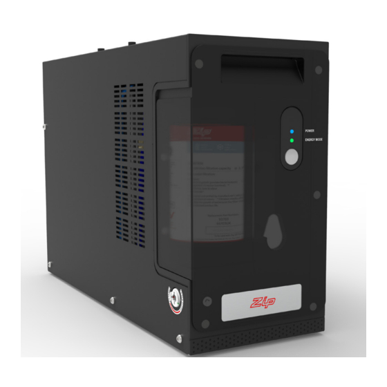
Operation Energy mode To enable/disable energy mode, press the button on the front of the command centre. The green light will illuminate when energy mode is enabled. POWER When energy mode is enabled, after 2 hours of ENERGY MODE inactivity, the boiling tank set point temperature is reduced to 68°C, to conserve energy. -
Page 18: Maintenance
Maintenance Water filter The Micro water filter has a 6 month usage capacity. The filter cartridge may require changing earlier depending on water quality, usage, or if you notice unpleasant odours or tastes. The Service icon on the tap will illuminate and “C F” will flash on the command centre LCD, to indicate a filter change is due. - Page 19 Maintenance While the LCD flashes “F”, press and hold the button. Water will flow through the filter and out the hose. The “F” displayed will stay on. Continue holding the button. The button may be released to temporarily stop water flow. After 2 minutes (10 litres), water flow will stop.
-
Page 20: Air Inlet Filter (Boiling/Chilled Model)
Maintenance Air inlet filter (Boiling/Chilled model) The air inlet filter screen should be inspected at least every three months, cleaned and replaced if damaged. Slide to remove the air inlet Rinse off with tap water. Gently dry with cloth/towel. filter screen Note: For best performance the Re-fit the air inlet filter screen unit should only be operated... -
Page 21: Troubleshooting
Error codes consist of the letter E, followed by 2 digits, displaying in sequence repeatedly. Call an electrician, a plumber, or Zip free call in Australia on 1800 638 633 for assistance, service, spare parts or enquiries. - Page 22 Communication detect a tap connected. side of the command centre. loss Water will not dispense from If issue persists, contact Zip tap. service Compressor running Check adequate ventilation. continuously for 30 minutes, Check chilled water is not and chilled tank is full.
-
Page 23: Cleaning
Cleaning Do not use strong, corrosive or abrasive cleaning materials. Stainless steel surfaces will show scratches if an abrasive cleaning product is used. Wipe clean the outer surfaces with a damp sponge or soft cloth. End of life disposal In order to help preserve our environment we ask that you dispose of this product correctly. - Page 24 Service Free Call: 1800 460 222 zipwater.com AU02691 The terms “Zip” and “HydroTap” are registered trade marks of Zip Water (Aust) Pty Ltd. Zip products described in this publication are manufactured under one or more patents and further patent applications are pending. WMKA00099...
Need help?
Do you have a question about the Micro BC and is the answer not in the manual?
Questions and answers