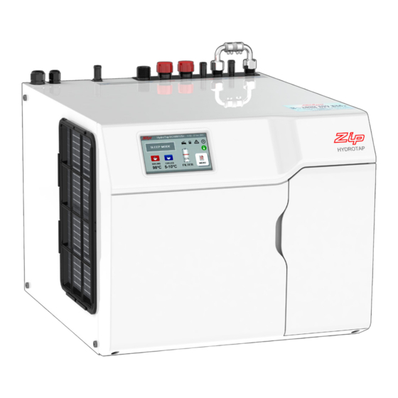
Zip HydroTap G4 Series Installation Instructions Manual
Filtered boiling and chilled drinking water for industrial kitchens and tea rooms
Hide thumbs
Also See for HydroTap G4 Series:
- User manual (32 pages) ,
- Installation instructions manual (32 pages) ,
- Installation instructions manual (20 pages)
Table of Contents
Advertisement
Installation instructions
Zip HydroTap G4
®
Filtered boiling and chilled drinking water for industrial kitchens and tea rooms.
VENTILATION IS
ESSENTIAL
Affix model number label
!
here
802742UK
READ
SECTION 2 'VENTILATION'
READ BEFORE YOU START
802742UK - G4 IS IT industrial installation instructions - Jan. 2016 - V2.03
Page 1 of 32
Advertisement
Table of Contents


Need help?
Do you have a question about the HydroTap G4 Series and is the answer not in the manual?
Questions and answers